
Subsea Field Architecture

a technology of subsea field and submerged structure, which is applied in the direction of insulation, wellbore/well accessories, construction, etc., can solve the problems of reducing the flow of well fluid to the offsite production and/or processing facility. , to achieve the effect of preventing the formation of hydrates

Inactive Publication Date: 2019-09-12
FMC TECH INC
View PDF9 Cites 4 Cited by
  • Summary
  • Abstract
  • Description
  • Claims
  • Application Information

AI Technical Summary

Benefits of technology

The present disclosure is about a new way to produce oil and gas offshore that solves issues with previous methods. It uses flexible tubes instead of rigid ones, which helps to prevent the formation of hydrates and saves money. The method also eliminates the need for redundant flowlines and flying leads, making it more efficient and cost-effective.

Problems solved by technology

In addition, rigid flowline jumpers are relatively heavy, expensive to manufacture and difficult to handle, and they typically require special equipment to install.
Furthermore, in certain subsea fields a risk exists that hydrates may form in the flowlines.
If this happens, the flow of well fluids to the offsite production and / or processing facility may be substantially diminished or even blocked.
As may be appreciated, the use of redundant flowlines greatly increases the cost and time to construct the subsea field.
However, flying leads are difficult and time consuming to install and are subject to being tangled and damaged.
If a flying lead becomes damaged, control of that tree is usually lost until the flying lead can be replaced.

Method used


Image

  • Subsea Field Architecture
  • Subsea Field Architecture
  • Subsea Field Architecture

Examples


Embodiment Construction

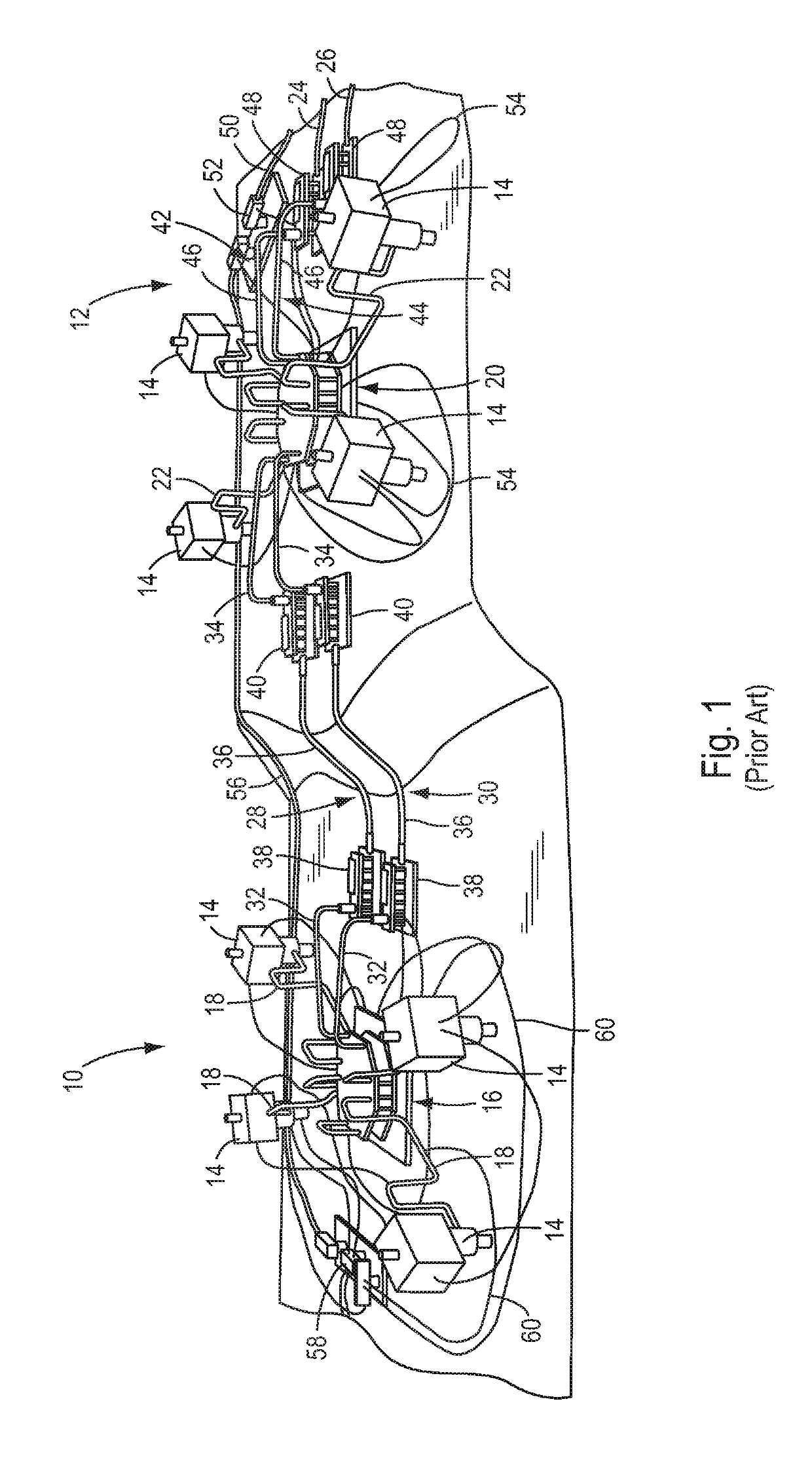
[0028]As background for the present disclosure, an example of a prior art subsea oil or gas field will be described with reference to FIG. 1. The prior art oil or gas field includes a plurality of subsea wells which are arranged into two sub-fields 10 and 12. As shown in FIG. 1, for example, each sub-field 10, 12 has four subsea wells. Each well comprises a wellhead on which is mounted a corresponding subsea christmas tree 14. Each tree 14 in the first sub-field 10 is connected to a first manifold 16 by a corresponding flowline jumper 18. Similarly, each tree 14 in the second sub-field 12 is connected to a second manifold 20 by a corresponding flowline jumper 22. The flowline jumpers 18, 22 are rigid pipes which must each be specifically designed to span the exact distance between a respective connection hub on the tree 14 and a corresponding connection hub on the manifold 16, 20.

[0029]The well fluids produced through the trees 14 are routed through the first and second manifolds 16...


PUM


Abstract

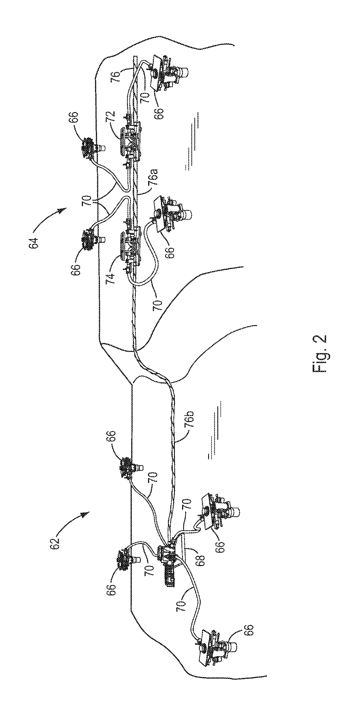
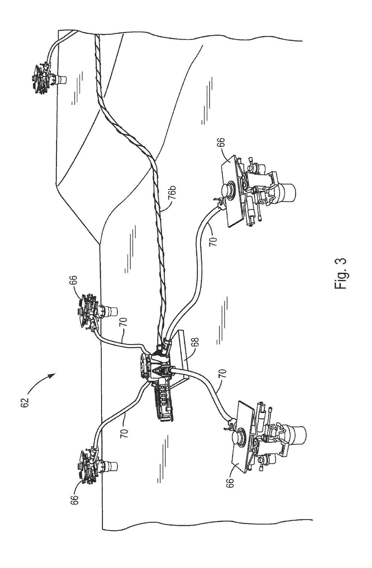
A subsea hydrocarbon production field includes a number of first subsea Christmas trees, a first manifold and a number of first flexible flowline jumpers, each of which is connected between the first manifold and a corresponding first tree. In one embodiment, Each first flowline jumper includes a first flow conduit and a number of first umbilical lines.

Description

[0001]The present application is based on and claims priority from U.S. Provisional Patent Application No. 62 / 383,199 filed on Sep. 2, 2016.[0002]The present disclosure is directed to a subsea oil or gas field. More particularly, the disclosure is directed to a subsea field which simpler, less costly and easier to install than prior art subsea fields.BACKGROUND OF THE DISCLOSURE[0003]Subsea hydrocarbon production fields typically comprise a plurality of christmas trees which are mounted on corresponding well bores. These trees may be arranged in more than one cluster, especially where the subterranean hydrocarbon formation extends over a substantial area. The trees in each cluster are often connected to a common manifold by respective flowline jumpers. In addition, the manifolds of the separate clusters may be connected together by corresponding flowlines. The well fluids produced by the several trees are commonly routed through their respective manifolds to a flowline end terminati...

Claims


Application Information

Patent Timeline
Patent Type & Authority Applications(United States)
IPC IPC(8): E21B43/017E21B36/00
CPCE21B36/00E21B43/017E21B33/035E21B43/00E21B36/005E21B43/013E21B15/00
Inventor HALVORSEN, TORECOUTO, PAULOMARION
Owner FMC TECH INC
Learn More