Injection mold, injection molding method, and molded article

Active Publication Date: 2019-08-22
HONDA MOTOR CO LTD
View PDF0 Cites 1 Cited by
  • Summary
  • Abstract
  • Description
  • Claims
  • Application Information

AI Technical Summary

Benefits of technology

The invention is about an injection mold and a way to make sure that two materials can meet and create a sharp boundary line between them, like a round chamfered shape. The method can also produce a molded article that has this boundary line.

Problems solved by technology

In this case, in the manufacturing of the instrument panel, a process of joining separately formed components or a painting process is required, resulting in an increase in manufacturing cost.

Method used


Image

  • Injection mold, injection molding method, and molded article
  • Injection mold, injection molding method, and molded article
  • Injection mold, injection molding method, and molded article

Examples


Embodiment Construction

[0018]Hereinafter, embodiments of the present invention will be described in detail with reference to the drawings.

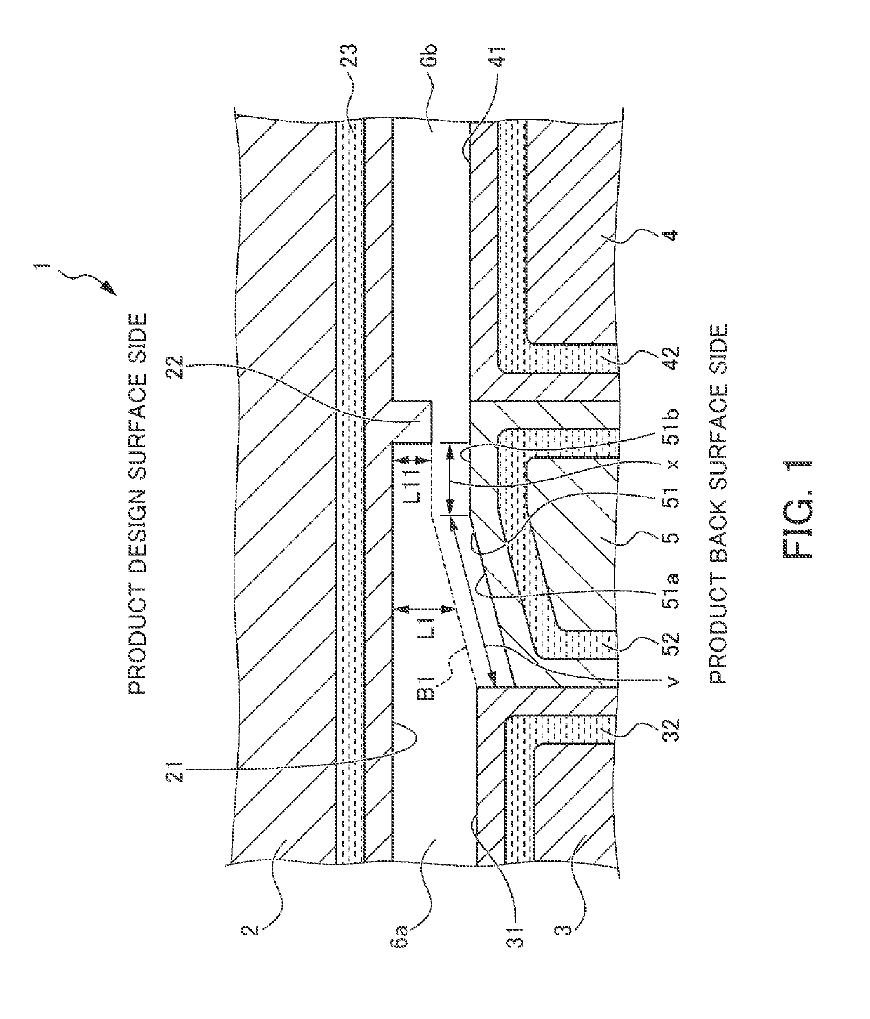
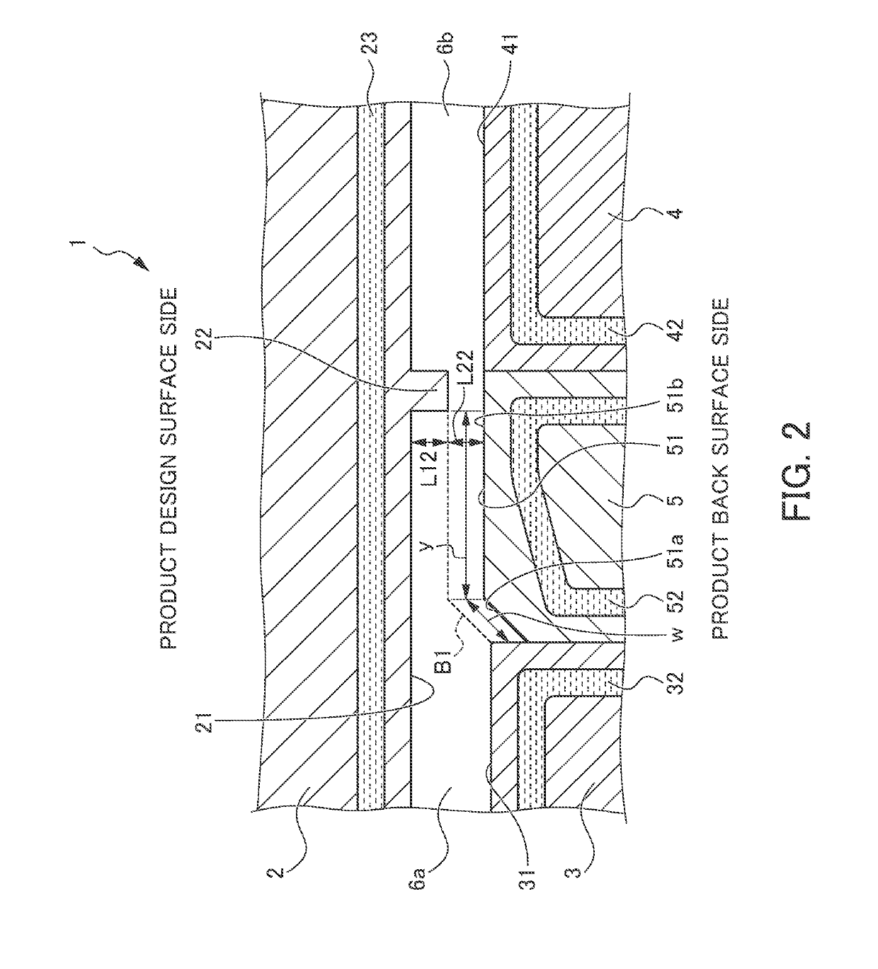
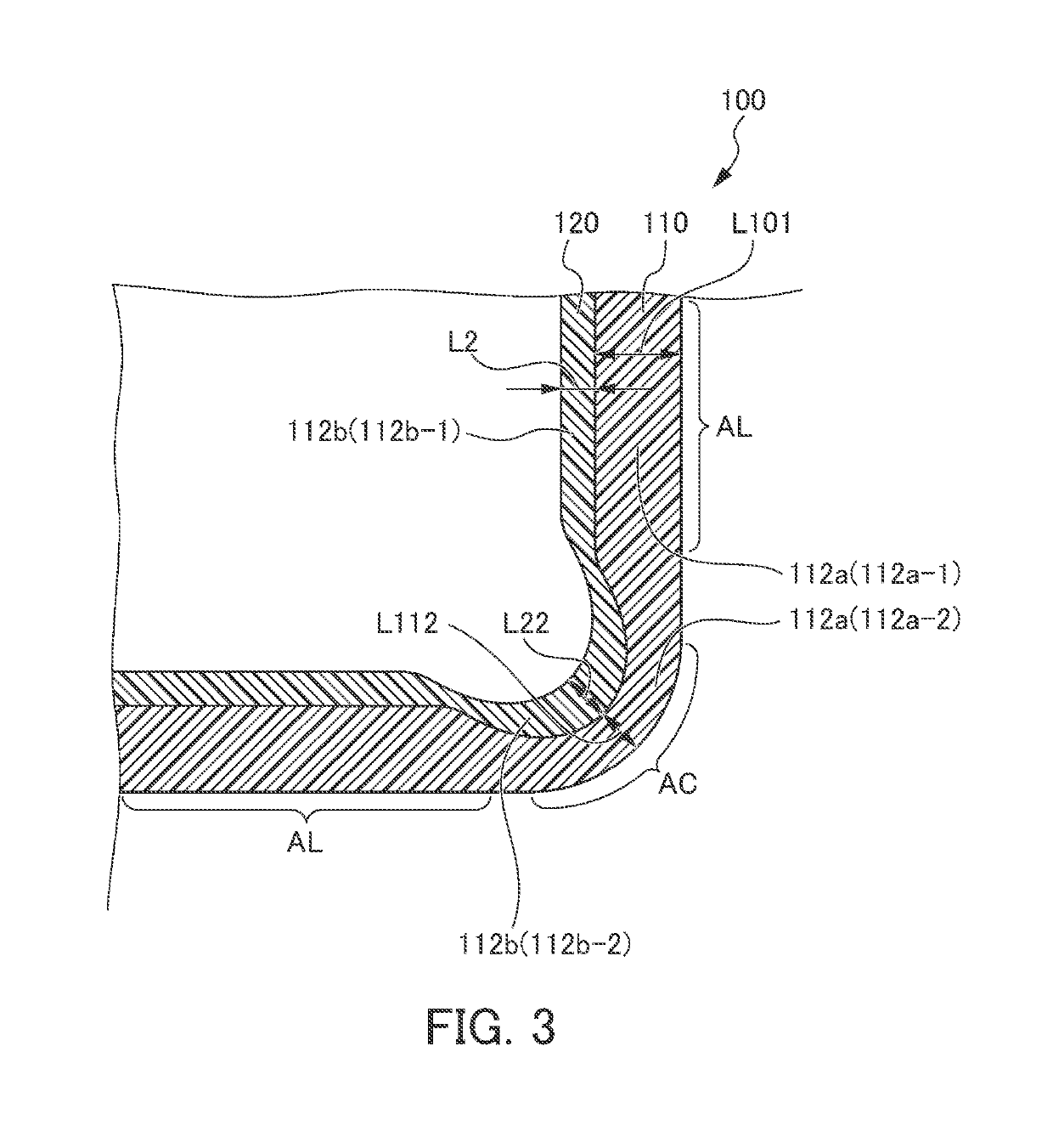
[0019]First, an injection mold 1 will be described. FIG. 1 is a cross-sectional view illustrating a portion of the injection mold 1 according to an embodiment of the present invention, that molds a linear part of a joining part 112 of a first material m1. FIG. 2 is a cross-sectional view illustrating a portion of an injection mold 1 according to the embodiment of the present invention, that molds a curved part of the joining part 112 of the first material m1. FIG. 3 is a cross-sectional view illustrating a first molded part 110 and a second molded part 120 of an instrument panel 100 as a molded article according to the embodiment of the present invention, illustrates a cross-sectional view taken along the line A-A in FIG. 4 in a portion indicated by a line AL in FIG. 3, and illustrates a cross-sectional view taken along the line B-B in FIG. 5 in a portion indicated by a...


PUM

PropertyMeasurementUnit
Lengthaaaaaaaaaa
Widthaaaaaaaaaa

Abstract

Provided are an injection mold and an injection molding method by which a boundary line between a first material and a second material curved so as to be sharply bent like a round chamfered shape can be formed reliably in a desired position, and a molded article molded using the injection mold and the injection molding method. The sum of a length w of an inclined-part forming part 51a and a length y of a thinned-part forming part 51b in a width direction of a linear part or a width direction of a curved part is at least equal to a prescribed value, and the thinned-part forming part 51b forming the curved part has a second length y longer than a first length in the width direction of the curved part.

Description

TECHNICAL FIELD[0001]The present invention relates to an injection mold, an injection molding method, and a molded article. More particularly, the present invention relates to an injection mold and an injection molding method for integrally molding a first material and a second material each having a different composition, and a molded article.BACKGROUND ART[0002]Conventionally, from viewpoint of a design, in an instrument panel of a vehicle, an upper surface portion and a lower surface portion are sometimes molded with materials of different colors. Further, the instrument panel sometimes attempts to reduce the material cost by forming an upper surface portion easily exposed to direct sunlight with a material excellent in heat resistance and molding a lower surface portion that is hard to be exposed to direct sunlight with a relatively inexpensive material. In such an instrument panel, for example, the upper surface portion and the lower surface portion are molded separately, or a ...

Claims


Application Information

Patent Timeline
IPC IPC(8): B29C45/16B29C45/26
CPCB29C45/1639B29C45/26B29L2031/3008B29C45/16B29C45/56B29C45/1635
Inventor HANAOKA, ATSUSHIYUSA, ATSUSHIWATANABE, TAKAHIROSAKAI, KENTAROKAWANO, KAZUHIROMIYAMOTO, HAJIME
Owner HONDA MOTOR CO LTD
Why Eureka
Try Eureka