Reduced-Pressure Type Backflow Preventer

a backflow preventer and reducer technology, applied in the field of pipeline valves, can solve the problems of time and materials consumption, components are prone to loosening, etc., and achieve the effects of facilitating cleaning and replacement of components, consuming time and materials, and convenient replacement and cleaning of components

Inactive Publication Date: 2019-08-15
GUANGDONG YONGQUAN VALVE TECH
View PDF5 Cites 4 Cited by
  • Summary
  • Abstract
  • Description
  • Claims
  • Application Information

AI Technical Summary

Benefits of technology

The patent text describes a new check valve design that makes it easier to install and detach the spring. The valve also includes bosses that can be fixedly mounted in the valve body, allowing for the easy adjustment of the spring. The technical effects of this design are improved convenience and ease of installation and detachment.

Problems solved by technology

The valve seat must be drilled and tapped, and then the components are fixedly mounted in the valve seat by means of threaded connection, which consumes time and materials.
Moreover, in the opening and closing process of the check valve, the components and the valve seat repeatedly vibrate, and the components are prone to loosening.

Method used


Image

  • Reduced-Pressure Type Backflow Preventer
  • Reduced-Pressure Type Backflow Preventer
  • Reduced-Pressure Type Backflow Preventer

Examples


Embodiment Construction

[0040]Hereinafter, further description is made to the present invention in combination with the accompany drawings and the detailed description.

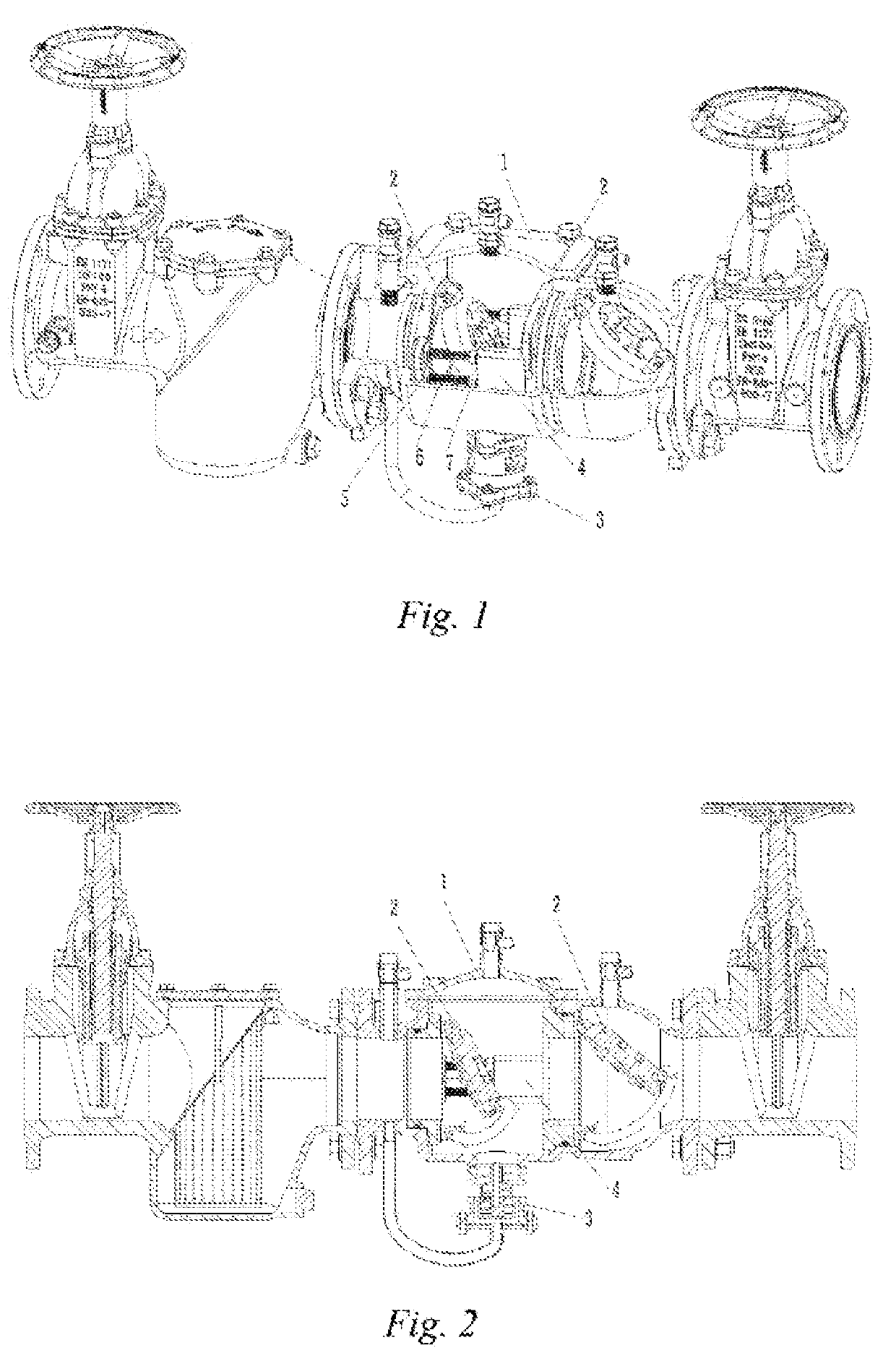
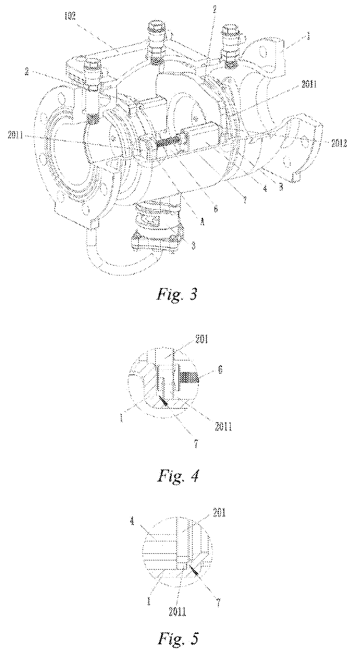
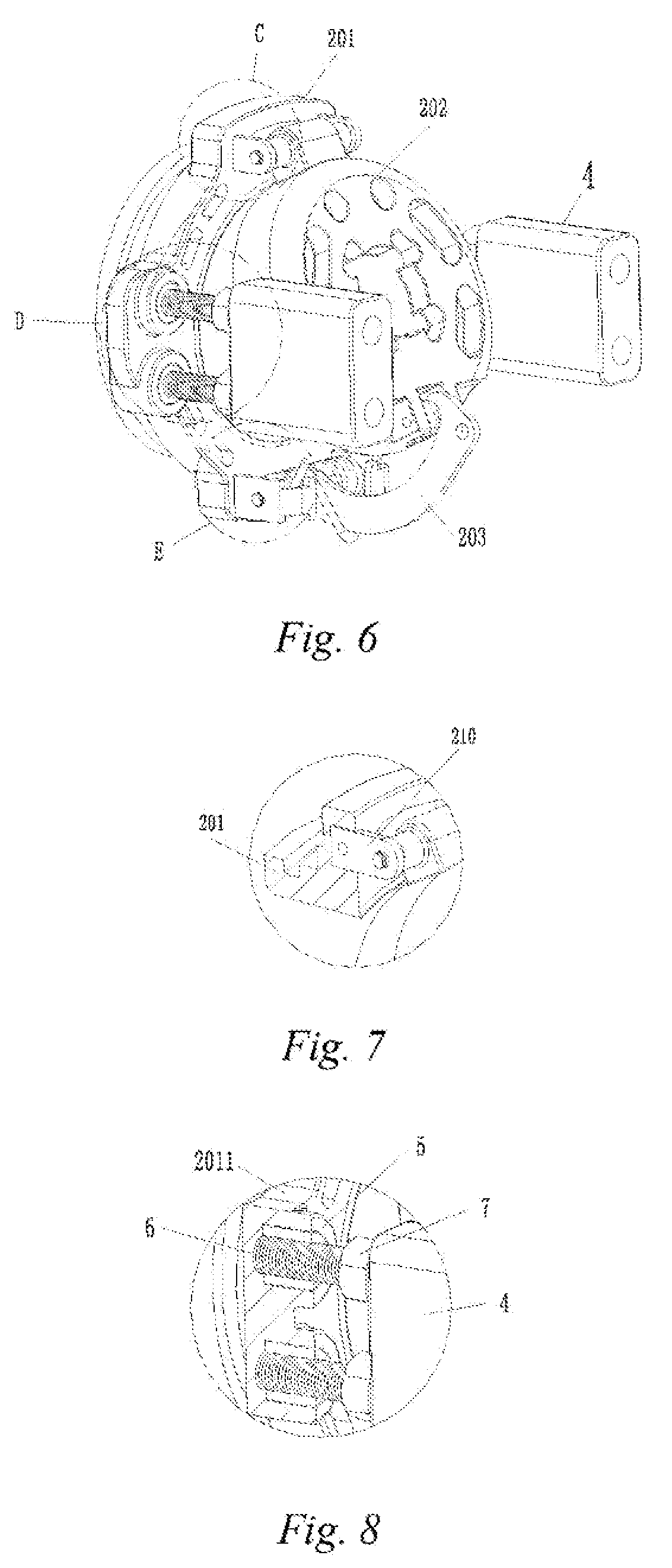
[0041]As shown in FIGS. 1-14, disclosed is a reduced-pressure type backflow preventer, comprising a valve body 1, two check valves 2 of the same structure, and a drain valve 3, wherein a cavity is formed inside the valve body, and a valve wall of the valve body is provided with a water inlet, a water outlet, and a drain opening; the two check valves are both fixedly mounted inside the valve body via a supporting member 4, and are positioned at the water inlet and the water outlet, respectively; the drain valve is mounted outside the valve body, and is positioned at the drain opening;

[0042]the check valve 2 comprises a valve seat 201, a valve clack 202, a rocking bar 203, and a twin torsional spring 204; one side of the valve clack is hinged to an upper end of the valve seat, and the other side of the valve clack is provided with a roller 205...


PUM


Abstract

Disclosed is a reduced-pressure type backflow preventer comprising a valve body (1), two check valves (2) of the same structure and a drain valve:(3) wherein a cavity is formed body, and a valve wall of the valve body is provided With a water inlet, a water outlet, and a drain opening; the two check valves are both fixedly mounted inside the valve body supporting member (4), and are positioned at the water inlet and the water outlet, respectively; the drain valve is mounted outside the valve body, and is positioned at the drain opening; the check valve comprises a valve seat (201), a valve clack (202), a rocking bar (203), and a twin torsional spring (204); one side of the valve clack is hinged to an upper end of the valve seat, and the other side is provided with a roller (205); the rocking bar is connected to a lower end of the valve seat via a pin (206); the roller abuts against the rocking bar and slides on the rocking bar; the twin torsional spring is sheathed over the pin; and a spring force of the twin torsional spring acts on the rocking bar to maintain the valve clack in a normally closed state, and an external force is used to cause the roller on the valve clack to roll on the rocking bar so as to open the valve clack. The preventer provides a better flow preventing effect by virtue of the structure of the twin torsional spring and the rocking bar of the check valve.

Description

TECHNICAL FIELD[0001]The present invention relates to the technical field of pipeline valves, and more particularly to a reduced-pressure type backflow preventer.BACKGROUND ART[0002]A backflow preventer is used for a pipeline for sewage treatment and other pipelines to prevent backflow pollution caused by backflow of liquid in the flow direction. The backflow preventer is a valve device formed by two separate check valves and one safety drain valve. The structure of the existing check valve is so simple that the resistance to water flow is very obvious. The resistance of the check valve to the water flow increases linearly as the opening degree of the valve clack increases, and the safety drain valve frequently drains water pressure cavities of the backflow preventer generate less pressure fluctuations.[0003]In addition, the valve seat of the domestic check valve basically adopts a metal material, and the fixed connection between components must be implemented by a traditional mecha...

Claims


Application Information

Patent Timeline
Patent Type & Authority Applications(United States)
IPC IPC(8): F16K1/20F16K1/42F16K1/52F16K11/10F16K15/03
CPCF16K11/105F16K1/42F16K1/523F16K1/205F16K15/033F16K1/2007F16K1/2028F16K15/035E03F7/04F16K15/1821
Inventor HUO, DAWENWU, BOMINLIANG, JIANLINCHEN, JIANMINGHE, GUOHAOLI, BIAOPAN, QINGXIANGHUANG, MINGLIANGOU, JIAXIAN
Owner GUANGDONG YONGQUAN VALVE TECH
Why Eureka
Try Eureka