
Coordinated frequency load shedding protection method using distributed electrical protection devices

a technology of distributed electrical protection devices and frequency load shedding, which is applied in the integration of power network operation systems, instruments, effective value measurements, etc., can solve the problems of system reducing the ability to respond to changes in frequency of ac signals as needed, periodic negative load from time to time, and inability to respond quickly to electrical power distribution networks

Active Publication Date: 2019-08-08
S&C ELECTRIC
View PDF0 Cites 3 Cited by
  • Summary
  • Abstract
  • Description
  • Claims
  • Application Information

AI Technical Summary

Benefits of technology

The patent describes a system and method for protecting and controlling an electrical power distribution network. It uses switch-gear assemblies along the lines to determine which loads receive the AC power signal and to prevent power from flowing in the reverse direction. The system monitors the frequency of the power signal to detect any sudden changes in frequency, indicating a problem with the network's stability. The switch-gear assembly then opens or remains closed based on the direction of power flow and the location of the assembly. The system can be used to load shedding, where excessive power demands are reduced to maintain network stability. The patent addresses the need for fast and reliable switch-gear apparatus to handle frequent frequency events that can occur in milliseconds.

Problems solved by technology

In addition, distributed generation sources may be interconnected with loads in distribution resulting in periods of negative load from time to time.
However, some electrical power distribution networks are limited in their ability to respond quickly enough to an underfrequency event, such as a loss of a major generator or an abrupt increase in loads being applied to the grid.
For example, certain power distribution networks, such as island grids, have a limited number of power plants that provide the power, and thus the system has a reduced ability to respond to changes in the frequency of the AC signal as needed.
Thus, since it is unknown in advance what loads may be producing power and at what time, removing those loads from the electrical grid during an underfrequency load shedding event may make an underfrequency transient worse and reduce the ability of the event to be quickly overcome since those loads were acting to support the frequency of the AC signal on the grid.
Hence, when an underfrequency condition is detected and load shedding is necessary, the current method of providing underfrequency load shedding via substation-based load shed is not precise in that large areas may be unnecessarily affected and loads generating power may be removed.
Further, there is also less available governor response in smaller grids and grids with a higher proportion of distributed generation to help dampen frequency oscillations that occur during a loss of generation or loss of load events.
Unlike central generation, distributed generation sources typically operate at maximum power and are not either able or not regulated via interconnection tariffs or controlled to provide governor response like central generation.
Moreover, if an underfrequency event occurs, and the underfrequency load shedding process removes large amounts of load to overcome the event, it is possible that removal of the loads could cause the frequency to go above 50 or 60 Hz, which could also cause similar stability control and have wide-area impact as in an underfrequency event.
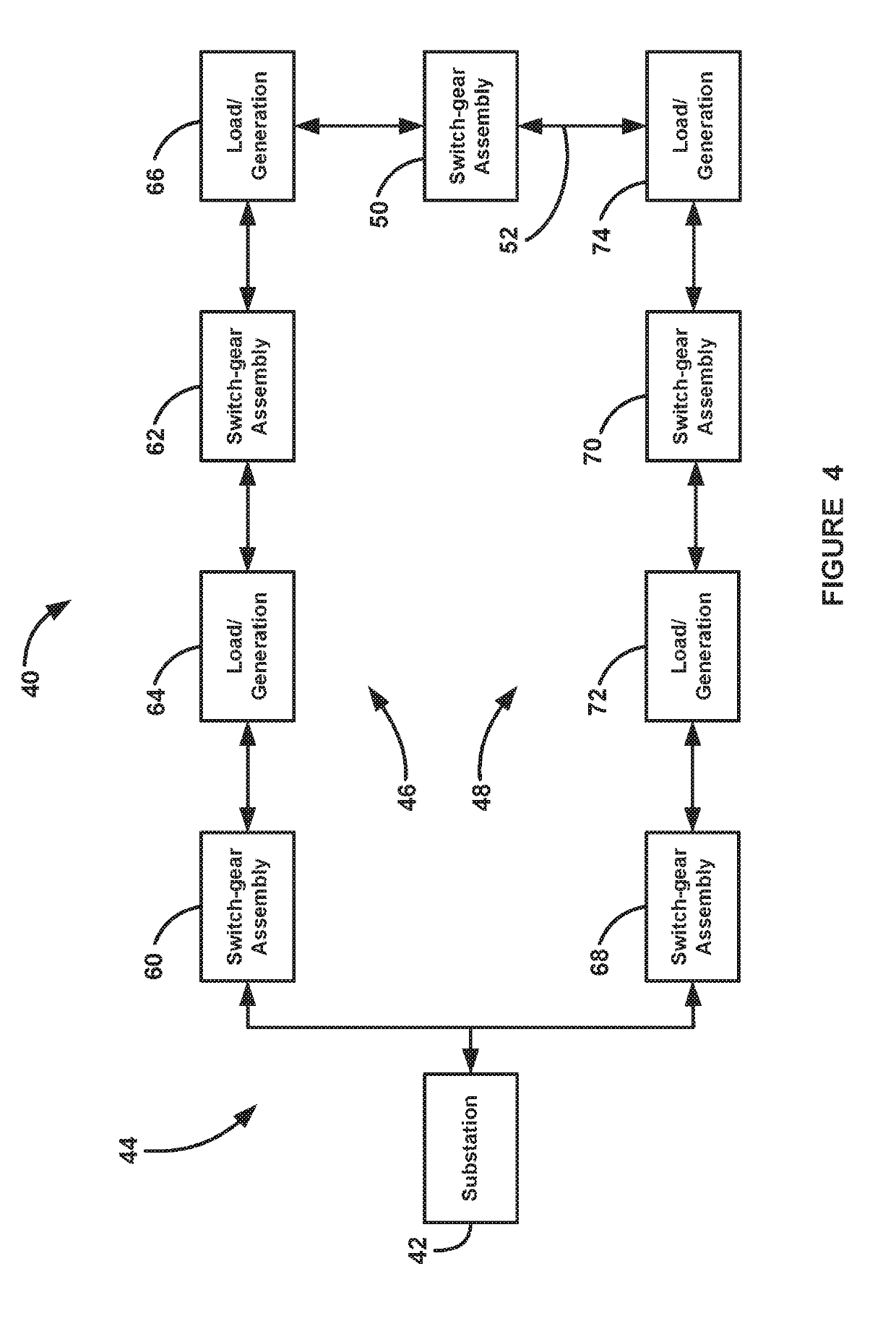
Furthermore, the order of operation of which switch-gear assembly opens first in response to the underfrequency event is determined by the location of the switch-gear assembly and a time delay, where those switch-gear assemblies that are farther from the power source are opened first to limit the number of loads that are affected by the underfrequency event.

Method used


Image

  • Coordinated frequency load shedding protection method using distributed electrical protection devices
  • Coordinated frequency load shedding protection method using distributed electrical protection devices

Examples


Embodiment Construction

[0015]The following discussion of exemplary embodiments directed to a system and method for providing frequency load shedding in an electrical power distribution network is merely exemplary in nature, and is in no way intended to limit the embodiments of the disclosure or applications or uses.

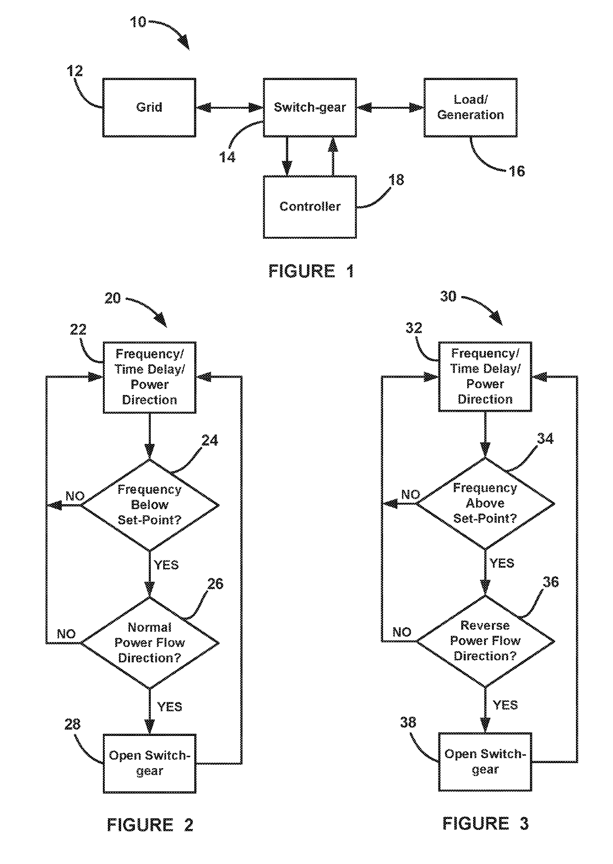
[0016]As will be discussed in detail below, a frequency load shedding scheme is disclosed for an electrical power distribution network that controls switch-gear at the outer edges of the network so that the number of loads that are removed from the network during a frequency event is limited. More specifically, switch-gear is distributed within a distribution network that supplies power to a group of loads. Each switch-gear detects a frequency event and which direction the power is flowing, i.e., is the group of loads providing power to the network. Thus, if the switch-gear determines that power is being provided to the network because the group of loads is generating more power than it is cons...


PUM


Abstract

A method for providing frequency load shedding in a power distribution network. The network includes a number of distributed switch-gear assemblies that control whether AC power is provided to groups of loads. The distributed switch-gear assemblies monitor the frequency of the AC signal to determine if a frequency event is occurring and also determine the direction of the power flow at the time of the event. The switch-gear assembly may open in an underfrequency event only if the loads are drawing power from the network, and the switch-gear assembly may open in an overfrequency event only if there is reverse power flow during the event. In addition, the order of operation of which switch-gear assemblies may open first in response to the frequency event is determined in advance by the location of the switch-gear assembly in the network and a corresponding time delay and coordinated frequency set-points.

Description

CROSS REFERENCE TO RELATED APPLICATION[0001]This application claims the benefit of priority from the U.S. Provisional Application No. 62 / 625,990, filed on Feb. 3, 2018, the disclosure of which is hereby expressly incorporated herein by reference for all purposes.BACKGROUNDField[0002]This disclosure relates generally to a frequency load shedding scheme for disconnecting load in an electrical power distribution network in response to an unusual frequency event and, more particularly, to a frequency load shedding scheme for removing load in an electrical power distribution network in response to a frequency event, where the scheme selectively opens certain switch-gear depending on the direction of the power flow at the switch-gear during the event, and where all of the switch-gear are calibrated and coordinated in advance with a control time-frequency delay so that those switch-gear at an outer edge of the network shed first and that the scheme does not require fast communications duri...

Claims


Application Information

Patent Timeline
Patent Type & Authority Applications(United States)
IPC IPC(8): H02J3/14
CPCH02J3/14H02H7/26H02H3/46H02J2310/12H02J2310/14Y04S20/222Y02B70/3225G01R19/2513G01R31/08H02H1/0007H02H1/0092H02H3/42H02J3/381H02J2300/24H02J2300/28H02J2310/60Y02E10/56G01R19/02G01R19/16528G01R19/2506H02H7/28H02J3/00
Inventor MATAMOROS, JOSEPH
Owner S&C ELECTRIC
Learn More