
Fluorescence detection instrument

a fluorescence detection and instrument technology, applied in the field of fluorescence detection instruments, can solve the problems of inability to meet the practical requirements of signal-to-noise ratio (snr) of such instruments, huge size and weight of such instruments, and huge intensity difference between excitation light and fluorescence light signal, so as to achieve superior performance for multiplexing qpcr applications, minimizing the size and weight of instruments, and high signal-to-noise ratio

Active Publication Date: 2019-08-08
DELTA ELECTRONICS INTL SINGAPORE
View PDF1 Cites 3 Cited by
  • Summary
  • Abstract
  • Description
  • Claims
  • Application Information

AI Technical Summary

Benefits of technology

The invention is a fluorescence detection instrument that has a high signal-to-noise ratio, which means it can detect small amounts of light accurately. This means that the instrument can be made smaller and lighter while still performing well. The instrument is also affordable and can be used for multiplexing qPCR application.

Problems solved by technology

There are a large number of fluorescent detection instruments known in the art that are employed to image fluorescence signals, but the bulky size and weight of such instruments are huge and the signal-to-noise ratio (SNR) thereof cannot meet the practical requirements.
On the other hand, another problem that all fluorescence detection instruments have in common is the huge intensity difference between the excitation light and the fluorescence light signal.
A large number of expensive optical devices have to be employed with respect to different excitation filters, respectively.
It is not convenient and the detection result will be influenced due to the temperature and reaction time changes.

Method used


Image

  • Fluorescence detection instrument
  • Fluorescence detection instrument
  • Fluorescence detection instrument

Examples


Embodiment Construction

[0049]The present invention will now be described more specifically with reference to the following embodiments. It is to be noted that the following descriptions of preferred embodiments of this invention are presented herein for purpose of illustration and description only; it is not intended to be exhaustive or to be limited to the precise form disclosed. For example, the formation of a first feature over or on a second feature in the description that follows may include embodiments in which the first and second features are formed in direct contact, and may also include embodiments in which additional features may be formed between the first and second features, such that the first and second features may not be in direct contact. In addition, the present disclosure may repeat reference numerals and / or letters in the various examples. This repetition is for the purpose of simplicity and clarity and does not in itself dictate a relationship between the various embodiments and / or ...


PUM

PropertyMeasurementUnit
Angleaaaaaaaaaa
Angleaaaaaaaaaa
Diameteraaaaaaaaaa

Abstract

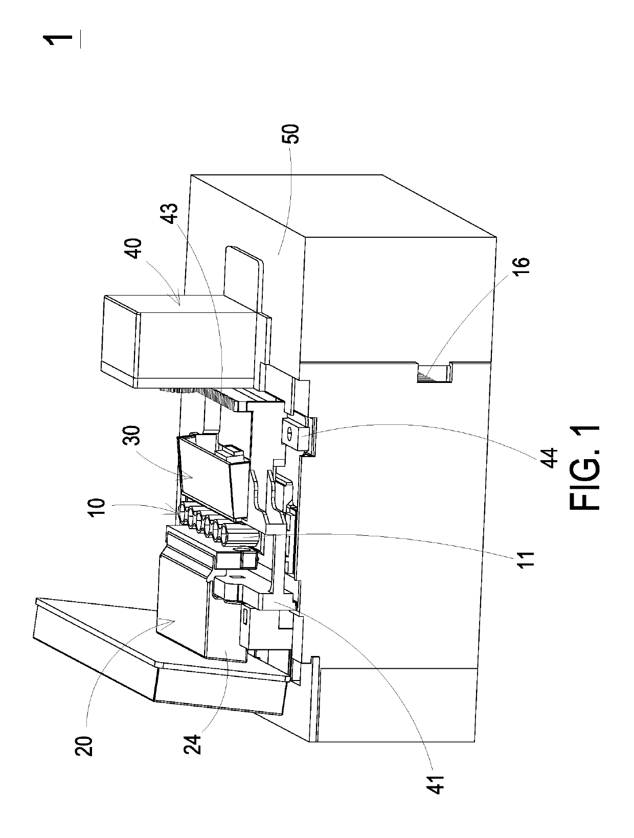
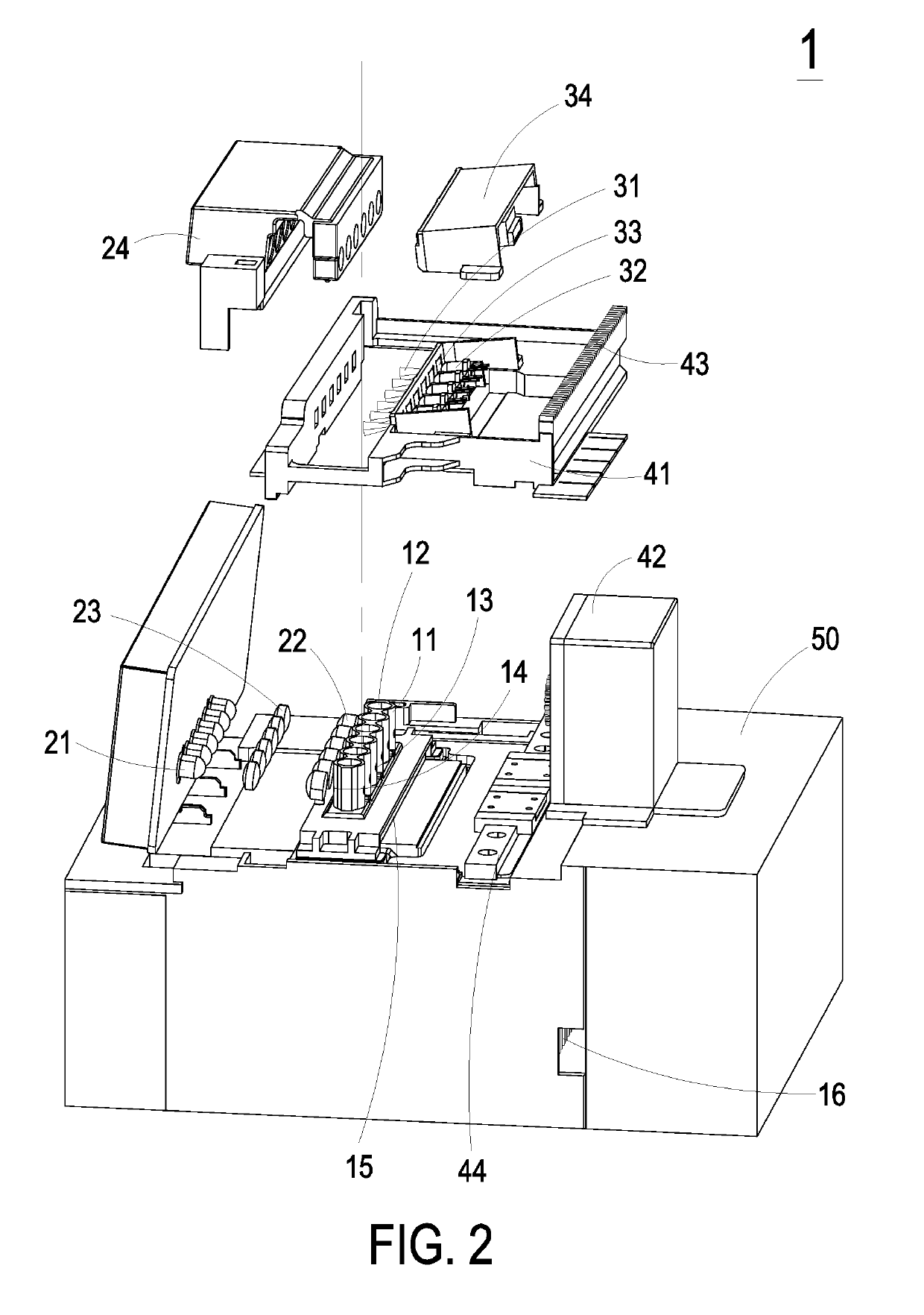
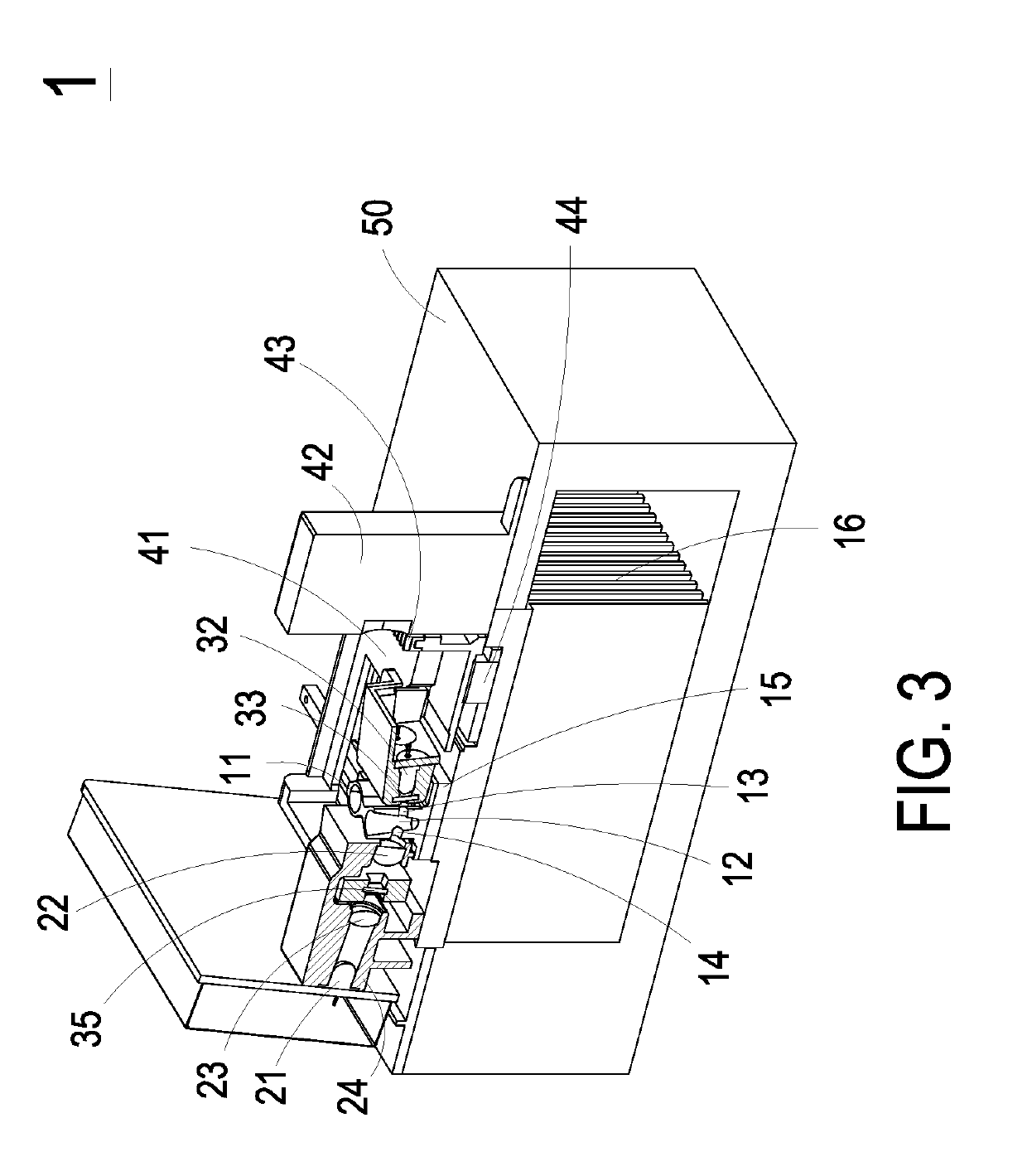
The disclosure relates to a fluorescence detection instrument, including a base, a heating module, a detecting module, an illumination module, and an actuation module. The heating module, the detecting module, and the actuation module are disposed on the base. The heating module includes plural heating holders, wherein each of the plural heating holders is adapted to accommodate a light-transmissive reaction container adapted to contain a fluorescent reaction mixture with at least one targeted fluorescent probe respectively. The detecting module is configured with the heating module to form plural detection channels, wherein the plural heating holders are located at the plural detection channels respectively. The actuation module is connected with the illumination module and adapted to drive the illumination module to move to at least one predetermined position to selectively match at least one combination of the heating holder on the corresponding detection channel.

Description

FIELD OF THE INVENTION[0001]The present invention relates to a fluorescence detection instrument, and more particularly to a fluorescence detection instrument with high signal-to-noise ratio for multiplexing qPCR application.BACKGROUND OF THE INVENTION[0002]The demand of acquiring large amounts of a specific segment of DNA efficiently for different purposes is booming in recent years. Among the entire existing DNA sequencing techniques, Polymerase Chain Reactions (PCR) is one of the most economical and straightforward techniques amplifying billion copies of targeted DNA segments in short period of time. The applications of PCR technique are broadly adopted, such as selective DNA isolation for genetic identification, forensic analysis for analyzing ancient DNA in archeology, medical applications for genetic testing and tissue typing, fast and specific diagnosis of infectious diseases for hospitals and research institutes, inspection of environmental hazards for food safety, genetic i...

Claims


Application Information

Patent Timeline
IPC IPC(8): G01N21/64C12Q1/686C12Q1/6851B01L7/00
CPCG01N21/6428C12Q1/686C12Q1/6851B01L7/52G01N2021/6439G01N2201/068B01L2300/0654B01L2300/1838B01L2300/0681G01N21/6486B01L9/06G01N21/645G01N2201/0407G01N21/0332G01N2021/6417
Inventor MA, BOYIU, JEI-YINHUANG, SONG-BINHUANG, PO-YAOLI, CHUN-JUNGKAO, YU-KAI
Owner DELTA ELECTRONICS INTL SINGAPORE
Learn More