Synchronous reluctance machine

a synchronous and reluctance machine technology, applied in the field of electromechanical engineering, can solve the problems of failure to achieve maximum rotor anisotropy, low energy characteristics (efficiency, power factor, specific torque, etc.), and achieve the effect of improving the energy characteristics of the reluctance machine, in particular power factor, efficiency, specific torque and specific power

Inactive Publication Date: 2019-08-01
EMACH LLC
View PDF5 Cites 1 Cited by
  • Summary
  • Abstract
  • Description
  • Claims
  • Application Information

AI Technical Summary

Benefits of technology

[0009]This results in improved energy characteristics of the reluctance machine, in particular power factor, efficiency and specific power thereof for the same number of flux barriers.
[0025]The increased gap provides better energy characteristics of the reluctance machine, in particular power factor, efficiency, specific torque and specific power.

Problems solved by technology

However, this machine fails to achieve maximum rotor anisotropy at equal number of flux barriers, which leads to low energy characteristics (efficiency, power factor, specific torque).
This machine fails to achieve maximum rotor anisotropy, and therefore its energy characteristics (efficiency, power factor) are low.
Disadvantageously, this machine has a lower rotor anisotropy value for a fixed number of flux barriers, and therefore, low energy characteristics (efficiency, power factor) and low specific characteristics (specific torque and specific power).

Method used


Image

  • Synchronous reluctance machine
  • Synchronous reluctance machine
  • Synchronous reluctance machine

Examples


Embodiment Construction

[0035]The embodiments of the disclosed synchronous reluctance machine (SynRM) are aimed at increasing its energy characteristics (efficiency, specific torque and specific power) for a fixed number of flux barriers.

[0036]In one embodiment, the SynRM comprises a stator with a winding arranged within stator slots, and a rotor mounted to provide a gap between the rotor and the stator, the rotor being rotatable with respect to the stator. Stator winding can be distributed or concentrated.

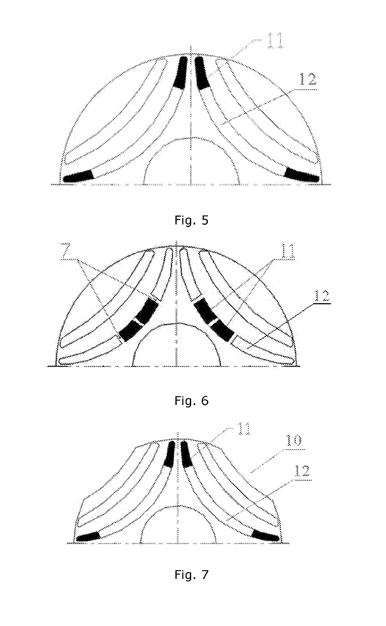
[0037]FIG. 1 illustrates a rotor structure. In one embodiment, the rotor is a steel cylinder comprised of sheets with transverse lamination. The rotor comprises alternatingly arranged magnetically permeable layers 1 (i.e., layers of high magnetic permeability) and flux barriers 2, 8 and 9 (i.e., layers of low magnetic permeability). Axis 4 of high magnetic permeability is defined as the d-axis, and axis 5 of low magnetic permeability is defined as the q-axis. The flux barriers 2, 8 and 9 are formed by cu...


PUM


Abstract

The present invention relates to electrical engineering, particularly to synchronous reluctance machines, and can be used in electrical drives for machines and mechanisms, as well as in electrical power generators. The synchronous reluctance machine comprises a stator with a winding arranged within stator slots, and a rotor mounted to provide a gap between the rotor and the stator, the rotor being rotatable with respect to the stator and comprising radially alternating magnetically permeable layers and flux barriers, wherein each barrier comprises at least one peripheral end extending towards the circumferential rotor surface and the angular pitch of the peripheral ends decreases in circumferential direction from the peripheral ends of the outer barriers towards the peripheral ends of the deepest inner barriers among at least three circumferentially sequential peripheral ends, wherein at least two of said ends are inner barrier ends. This results in improved energy characteristics of the reluctance machine, in particular power factor, efficiency and specific power thereof, for the same number of flux barriers. This is further achieved by a synchronous reluctance machine comprising a stator with a winding arranged within stator slots, and a rotor mounted to provide a gap between the rotor and the stator, the rotor being rotatable with respect to the stator and comprising radially alternating magnetically permeable layers and flux barriers, the gap is increased by 15-400% between the surface of the most external magnetically permeable layer and the stator compared to other sections of the gap.

Description

FIELD OF THE INVENTION[0001]The present invention relates to electronic engineering, particularly to synchronous reluctance machines, and can be used in electrical drives for machines and mechanisms, as well as in electrical power generators.BACKGROUND OF THE INVENTION[0002]Synchronous reluctance machines are machines with a magnetically inhomogeneous rotor. The main idea for creating torque (rotational torque) in a synchronous reluctance machine is based on that the rotor tends to be oriented in a position providing maximum magnetic permeability to the magnetic field of the stator. Synchronous reluctance machines can be implemented without magnets in rotor structure or with magnets in the rotor.[0003]Energy and specific characteristics of a synchronous reluctance machine can be improved by adding magnets to the rotor structure. The main idea for creating torque (rotational torque) remains identical to that of a synchronous reluctance machine without magnets in the rotor.[0004]A syn...

Claims


Application Information

Patent Timeline
Patent Type & Authority Applications(United States)
IPC IPC(8): H02K1/24H02K1/27
CPCH02K1/246H02K2213/03H02K1/276H02K21/025H02K1/20H02K19/06
Inventor DMITRIEVSKII, VLADIMIR ALEKSANDROVICHPRAKHT, VLADIMIR ALEKSEEVICH
Owner EMACH LLC
Why Eureka
Try Eureka