
Compliant Stylus Interaction

a stylus and interaction technology, applied in the field of stylus interaction, can solve the problems of touch system not having a progressive and consistent response to an applied stylus stroke, feeling unresponsive to varying contact strength, and adding an electromagnetic sensor, etc., to achieve good touch separation, natural user experience, and good all-round resolution

Active Publication Date: 2019-07-25
BEECHROCK LTD
View PDF15 Cites 14 Cited by
  • Summary
  • Abstract
  • Description
  • Claims
  • Application Information

AI Technical Summary

Benefits of technology

The patent is for a method to detect touch on tablet devices using infrared light beams. The distance between the lights and detectors should be between 1-12 millimeters for optimal resolution and touch separation. The strength of the touch can be measured based on the amount of light attenuation caused by the touch, allowing for a more natural user experience. For example, in a drawing application, the thickness of the lines can be adjusted based on the intensity of touch. This technology provides a more precise and immersive user experience for tablet devices.

Problems solved by technology

However, stylus operations on capacitive touch systems require a conductive tip and feel unresponsive to varying contact strength.
However, adding an electromagnetic sensor drives up the cost and power consumption of the stylus.
Despite these solutions, touch systems can still lack a progressive and consistent response to an applied stylus stroke.
Furthermore, the requirement to regularly replace batteries for these active styli can be a cause for user frustration and additional expense.
Touch events disturb the optical energy transfer from emitter to detector.

Method used


Image

  • Compliant Stylus Interaction
  • Compliant Stylus Interaction
  • Compliant Stylus Interaction

Examples


Embodiment Construction

I. Introduction

[0040]A. Device Overview

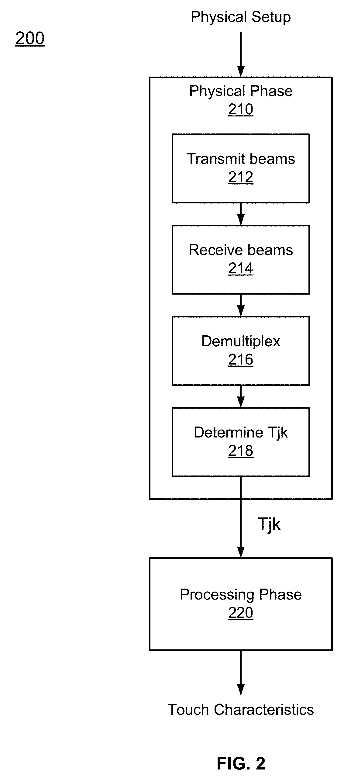
[0041]FIG. 1 is a diagram of an optical touch-sensitive device 100, according to one embodiment. The optical touch-sensitive device 100 includes a controller 110, emitter / detector drive circuits 120, and a touch-sensitive surface assembly 130. The surface assembly 130 includes a surface 131 over which touch events are to be detected. For convenience, the area defined by surface 131 may sometimes be referred to as the active area or active surface, even though the surface itself may be an entirely passive structure. The assembly 130 also includes emitters and detectors arranged along the periphery of the active surface 131. In this example, there are J emitters labeled as Ea-EJ and K detectors labeled as D1-DK. The device also includes a touch event processor 140, which may be implemented as part of the controller 110 or separately as shown in FIG. 1. A standardized API may be used to communicate with the touch event processor 140, for example b...


PUM


Abstract

A touch sensitive surface has emitters and detectors arranged around a periphery of the touch sensitive surface. The emitters produce optical beams that are received by the detectors. A stylus is configured to disturb one or more of the optical beams by a variable amount when in contact with the touch sensitive surface. The variable amount depends on an amount of force applied to the stylus towards the touch sensitive surface. A controller of the touch sensitive surface is configured to determine the touch strength of a touch event performed by the stylus based on disturbances of one or more of the optical beams. The touch strength provides a measure of the amount of force applied to the stylus.

Description

CROSS REFERENCE TO RELATED APPLICATIONS[0001]This application claims the benefit of priority to U.S. Provisional Patent Application No. 62 / 620,927, filed on Jan. 23, 2018, which is incorporated herein by reference in its entirety for all purposes.BACKGROUND1. Field of Art[0002]This description generally relates to a stylus interacting with a surface of touch-sensitive device, and specifically to a stylus configured to disturb optical beams by a variable amount dependent on an amount of force applied to the stylus towards the surface of the device.2. Description of the Related Art[0003]Touch-sensitive displays for interacting with computing devices are becoming more common. A number of different technologies exist for implementing touch-sensitive displays and other touch-sensitive devices. Examples of these techniques include, for example, resistive touch screens, surface acoustic wave touch screens, capacitive touch screens and certain types of optical touch screens.[0004]While touc...

Claims


Application Information

Patent Timeline
Patent Type & Authority Applications(United States)
IPC IPC(8): G06F3/042G06F3/0354G06F3/041
CPCG06F3/0421G06F3/03545G06F3/0416G06F3/048
Inventor O'CLEIRIGH, NIALLDRUMM, OWENMATHIS, OLIVIERKORCHAGIN, DANILKOLUNDZIJA, MIHAILOBOURBON, FREDERICPIOT, JULIEN
Owner BEECHROCK LTD
Learn More