Vehicular lamp
- Summary
- Abstract
- Description
- Claims
- Application Information
AI Technical Summary
Benefits of technology
Problems solved by technology
Method used
Image
Examples
first modified embodiment
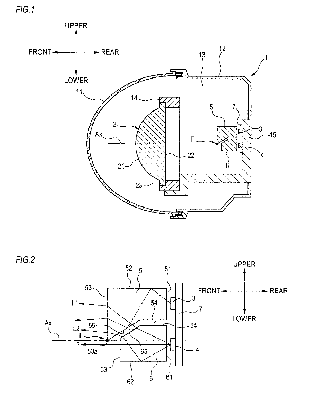
[0063]Subsequently, a first modified embodiment of the first light guide lens 5 and the second light guide lens 6 described in the above embodiment is described with reference to FIGS. 6 to 10. Since the parts denoted with the same reference numerals as the above embodiment have the same functions, the overlapping descriptions thereof are omitted.
[0064]As shown in FIG. 6, a first light guide lens 5A (an example of the first light guide member) and a second light guide lens 6A (an example of the second light guide member) of the first modified embodiment have a lens array configuration where a plurality of (five, in the present example) lenses 70a to 70e; 80a to 80e is coupled in a lateral direction (the right and left direction), respectively.
[0065]The lenses 70a to 70e, 80a to 80e are a biconvex lens of which a front surface and a rear surface are convex surfaces, respectively. The lenses 70a to 70e configuring the first light guide lens 5A are disposed with being superimposed abov...
second modified embodiment
[0070]Subsequently, a second modified embodiment of the first light guide lens 5 and the second light guide lens 6 of the above embodiment is described with reference to FIG. 11. Since the parts denoted with the same reference numerals as the above embodiment have the same functions, the overlapping descriptions thereof are omitted.
[0071]As shown in FIG. 11, a light guide lens 5B (an example of the first light guide member) of the second modified embodiment is configured to function not only as the first light guide lens 5 of the above embodiment on which the light of the first light source 3 is incident but also as the second light guide lens 6 of the above embodiment on which the light of the second light source 4 is incident. Also, the light guide lens 5B is configured to function as the projection lens 2.
[0072]The light guide lens 5B has a first incidence surface portion 51B, a total reflection surface portion 55B, and an edge portion 53Ba. The edge portion 53Ba corresponds to t...
third modified embodiment
[0074]Subsequently, a third modified embodiment of the first light guide lens 5 and the second light guide lens 6 of the above embodiment is described with reference to FIG. 12. Since the parts denoted with the same reference numerals as the above embodiment have the same functions, the overlapping descriptions thereof are omitted.
[0075]As shown in FIG. 12, a light guide lens 5C (an example of the first light guide member) of the third modified embodiment has a similar function to the first light guide lens 5 of the above embodiment. The light guide lens 5C has a first incidence surface portion 51C, a first emission surface portion 53C, a lower end edge 53Ca, and a total reflection surface portion 55C.
[0076]The first light source 3 and the second light source 4 are respectively attached on a substrate 7c and a substrate 7d in a state where the light-emitting surfaces thereof face toward the lamp front. A parabolic reflector 91 is attached on the substrate 7d of the second light sour...
PUM
 Abstract
Description
Claims
Application Information
 - R&D
- Intellectual Property
- Life Sciences
- Materials
- Tech Scout
- Unparalleled Data Quality
- Higher Quality Content
- 60% Fewer Hallucinations
Browse by: Latest US Patents, China's latest patents, Technical Efficacy Thesaurus, Application Domain, Technology Topic, Popular Technical Reports.
© 2025 PatSnap. All rights reserved.Legal|Privacy policy|Modern Slavery Act Transparency Statement|Sitemap|About US| Contact US: help@patsnap.com


