
Position measuring device

Active Publication Date: 2019-07-18
DR JOHANNES HEIDENHAIN GMBH
View PDF0 Cites 0 Cited by
  • Summary
  • Abstract
  • Description
  • Claims
  • Application Information

AI Technical Summary

Benefits of technology

The present invention provides a high-resolution position-measuring device that is tolerant to mounting and operating tolerances and immune to contamination. The device includes a measuring scale with a raster of stripe elements arranged along a measuring direction. The scanning unit includes a two-dimensional detector system with multiple detector columns having multiple detector elements in each case, which makes it possible to generate at least three periodic partial incremental signals and an absolute-position signal with regard to relative movements along the measuring direction. The absolute-position encoding provides for only slight interference in the periodic incremental signals, which allows for high-resolution position measurement. The provided single-field scanning both of the periodic raster and the absolute-position encoding in a direction transverse thereto provides for high insensitivity or robustness with respect to contamination of the measuring scale.

Problems solved by technology

A disadvantage of this system, for one, is the low tolerance in response to relative displacements of the measuring scale and scanning unit perpendicular to the measuring direction.
For another, there is also only low tolerance with regard to a possible relative rotation between the measuring scale and the scanning unit about an axis perpendicular to the plane of the measuring graduation.
Disadvantageous in this system are in particular its low displacement tolerances perpendicular to the measuring direction and also the required complex image processing.
A disadvantage of this device is that it allows only for a relatively low-resolution absolute position measurement.
Moreover, due to the only very small scanning field, the scanning is very susceptible to contamination.

Method used


Image

  • Position measuring device
  • Position measuring device
  • Position measuring device

Examples


Embodiment Construction

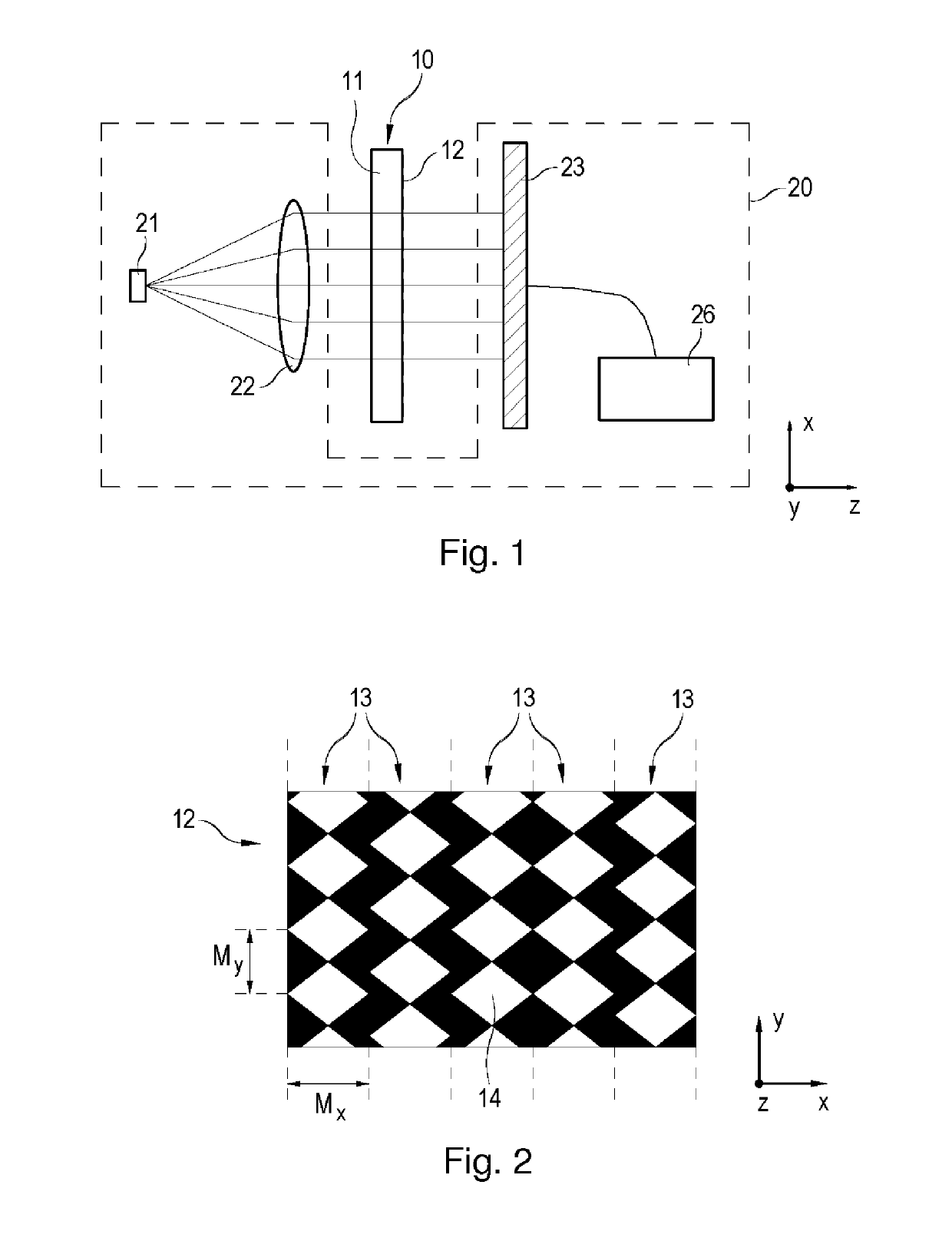
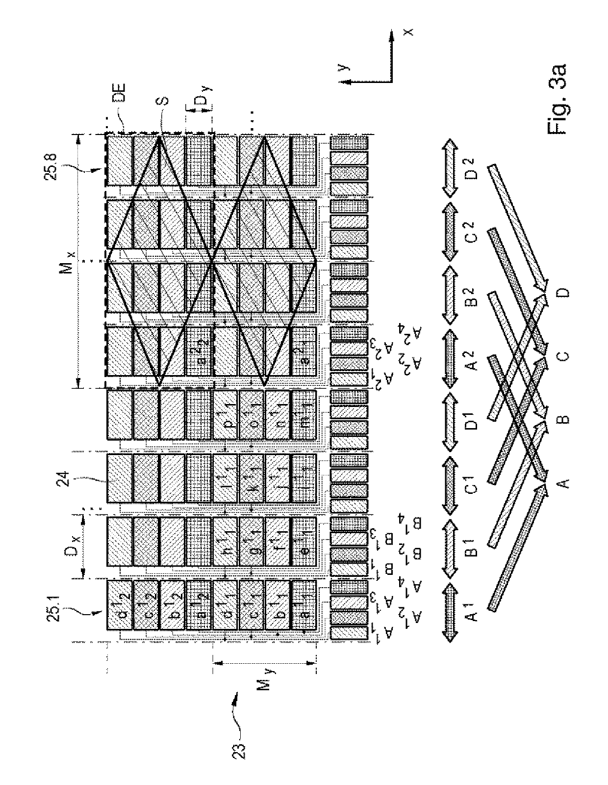
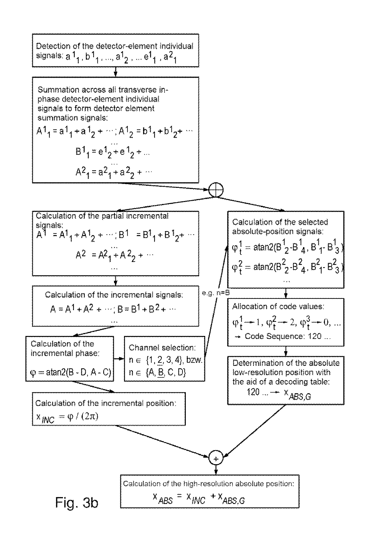
[0046]A position-measuring device determining an absolute position according to an example embodiment of the present invention, which is configured as an optical position-measuring device, is described with reference to FIGS. 1, 2, 3a, 3b, and 4a to 4f. FIG. 1 schematically illustrates the scanning-beam path, FIG. 2 is a plan view of a part of the measuring graduation on the measuring scale, and FIG. 3a is a plan view of a part of the detector system. Possible signal processing is described with reference to FIGS. 3b and 4a to 4f.

[0047]The position-measuring device may be used for an absolute position measurement along a linear measuring direction x. Disposed along measuring direction x are a measuring scale 10 and a scanning unit 20 in a manner that allows for a movement relative to each other within a specific measuring track. For example, measuring scale 10 may be stationary and scanning unit 20 may be movable; a reverse arrangement is possible as well. Measuring scale 10 and sc...


PUM


Abstract

A position-measuring device for determining an absolute position includes a measuring scale and a scanning unit that is movable relative to the measuring scale along at least one measuring direction. To generate a scannable signal pattern, the measuring scale has a measuring graduation which includes a raster of stripe elements arranged along the measuring direction at a measuring-scale longitudinal period. For the encoding of an absolute position, the stripe elements have a periodic structure having a measuring-scale transverse period along a transverse direction that is oriented perpendicular to the measuring direction. For scanning the signal pattern, the scanning unit has a two-dimensional detector system having a plurality of detector elements, which includes multiple detector columns having a plurality of detector elements in each case. The detector columns are periodically arranged along the measuring direction and the detector elements are periodically arranged along the transverse direction, so that by scanning the signal pattern, at least three periodic partial incremental signals are able to be generated with regard to relative movements along the measuring direction, as well as at least one absolute-position signal per detector column.

Description

CROSS-REFERENCE TO RELATED APPLICATIONS[0001]The present application claims priority to Application No. 10 2018 200 449.8, filed in the Federal Republic of Germany on Jan. 12, 2018, which is expressly incorporated herein in its entirety by reference thereto.FIELD OF THE INVENTION[0002]The present invention relates to a position-measuring device, which is, for example, suitable for determining an absolute position in a highly precise manner.BACKGROUND INFORMATION[0003]Certain position-measuring devices for determining an absolute position are conventional. On the one hand, for example, certain conventional systems include a plurality of tracks on the side of the scanned measuring scale, which are disposed in parallel and have different measuring graduations, such as a track having an absolutely encoded measuring graduation and also one or a plurality of further tracks with incremental measuring graduations. By arithmetically processing the low-resolution absolute position information...

Claims


Application Information

Patent Timeline
IPC IPC(8): G01D5/245
CPCG01D5/2455G01B11/00G01D5/34776G01D5/34792G01D5/34746G01D2205/90
Inventor WEIS, STEFANFRESE, DANIELHOLZAPFEL, WOLFGANG
Owner DR JOHANNES HEIDENHAIN GMBH
Learn More