
Bayonet connection for connecting a connector to a tubular body, bayonet ring, and tubular body

a technology of bayonets and connectors, applied in the direction of adjustment joints, pipe joints, couplings, etc., can solve the problem of higher costs

Active Publication Date: 2019-07-04
VOLKSWAGEN AG
View PDF0 Cites 3 Cited by
  • Summary
  • Abstract
  • Description
  • Claims
  • Application Information

AI Technical Summary

Benefits of technology

The present invention provides a bayonet joint that can compensate for deviations in position of the connectors and the tubular body. The joint has a symmetrical internal and external bayonet contour, which ensures easy manufacturability and rotation of the joint. A rotationally symmetric design also ensures durability and allows for good compensation between the number of segments. These features make the joint easy to manufacture and use.

Problems solved by technology

If the proportion of these possible impermissible tolerance zone positions is too high for the cost effectiveness of the product, other connection types must then be chosen or stringent requirements must be placed on the positional and dimensional tolerances, which in turn entails higher costs.

Method used


Image

  • Bayonet connection for connecting a connector to a tubular body, bayonet ring, and tubular body
  • Bayonet connection for connecting a connector to a tubular body, bayonet ring, and tubular body
  • Bayonet connection for connecting a connector to a tubular body, bayonet ring, and tubular body

Examples


Embodiment Construction

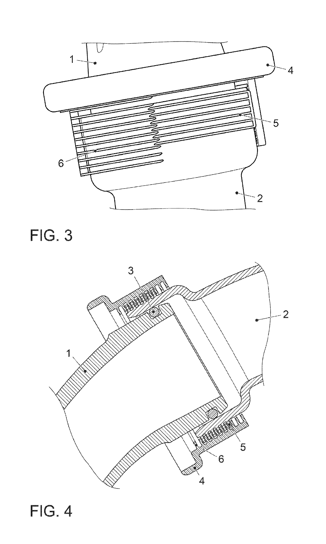
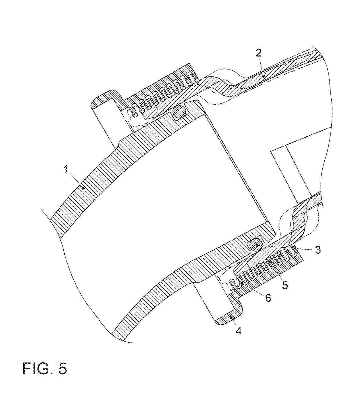
[0036]FIG. 1 shows a perspective view of an embodiment of a bayonet joint according to the invention in the unjoined state. A connector 1, which constitutes the tubular outlet of a compressor of an exhaust turbocharger of an internal combustion engine, has two bayonet tabs 7 that extend radially outward. The bayonet tabs 7 are rotationally symmetric about the central axis of the connector 1, and are implemented in two angular segments, which is to say that the bayonet tabs 7 do not surround the entire perimeter of the connector 1. The connector 1 is intended to be joined to the end of a tubular body 2, implemented as a pressure pipe of the internal combustion engine.

[0037]The tubular body 2 can be implemented as a pressure pipe serves to carry compressed fresh air downstream of the compressor towards the combustion chambers of the internal combustion engine. The tubular body 2 has an internal diameter that is dimensioned such that the tubular body 2 can surround the connector 1 in t...


PUM


Abstract

A bayonet joint is to be provided for joining a connector to a tubular body having the connector with bayonet tabs arranged on the exterior of the connector, the tubular body with at least one external bayonet contour arranged on the exterior of the tubular body, and a bayonet ring with inward facing bayonet hooks and at least one inward facing internal bayonet contour. In an assembled state of the bayonet joint the connector, tubular body, and bayonet ring are in a locking orientation relative to one another. The bayonet ring surrounds the connector and the tubular body in the radial direction on the outside, and secures the connector and the tubular body against removal from the bayonet ring.

Description

[0001]This nonprovisional application is a continuation of International Application No. PCT / EP2017 / 070103, which was filed on Aug. 8, 2017, and which claims priority to German Patent Application Nos. 10 2016 217 128.3, which was filed in Germany on Sep. 8, 2016 and 10 2016 224 088.9, which was filed in Germany on Dec. 5, 2016, and which are all herein incorporated by reference.BACKGROUND OF THE INVENTIONField of the Invention[0002]The present invention relates to a bayonet joint for joining a connector to a tubular body, a bayonet ring for use in such a bayonet joint, and a tubular body for use in such a bayonet joint.Description of the Background Art[0003]Bayonet joints are mechanical connections of two cylindrical (tubular) bodies that can be produced and released quickly. The bodies are joined by inserting one into the other and rotating them relative to one another about the longitudinal axis of the bodies. The joint is released by rotating the bodies relative to one another in...

Claims


Application Information

Patent Timeline
Patent Type & Authority Applications(United States)
IPC IPC(8): F16L37/248
CPCF16L37/248F01N13/1811F02B67/10F16L37/113F16L27/1274F16L27/12F16L37/252
Inventor DENEKE, MICHAEL
Owner VOLKSWAGEN AG
Learn More