Acoustic wave filter device, multiplexer, radio-frequency front-end circuit, and communication apparatus
- Summary
- Abstract
- Description
- Claims
- Application Information
AI Technical Summary
Benefits of technology
Problems solved by technology
Method used
Image
Examples
first preferred embodiment
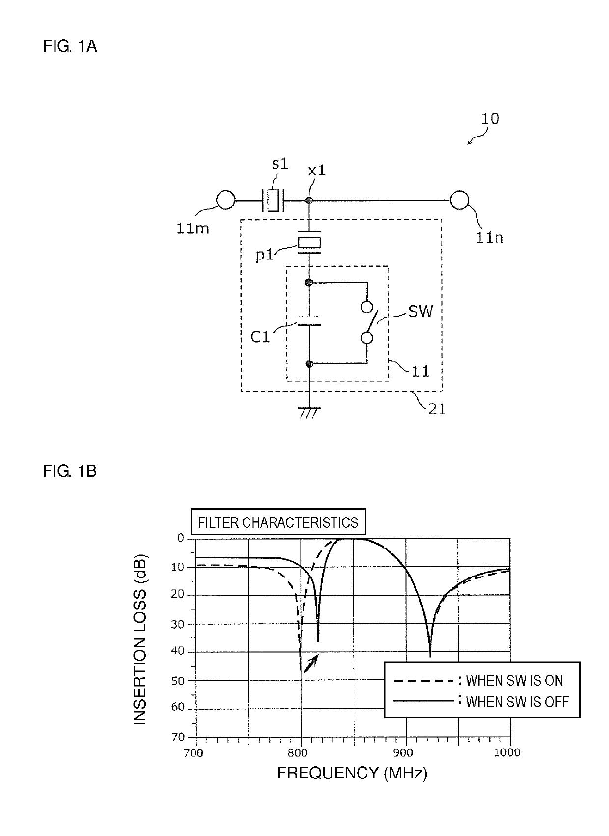
[0102]FIG. 1A is a circuit diagram of a filter 10 according to a first preferred embodiment of the present invention.
[0103]The filter 10 is a radio-frequency filter circuit disposed in a front-end portion of a multimode / multiband-support cellular phone, for example. The filter 10 is a band pass filter which is integrated in a multiband-support cellular phone compliant with the communication standards, such as 3GPP (Third Generation Partnership Project), and causes radio-frequency signals of a predetermined band to selectively pass through the filter 10. The filter 10 is an acoustic wave filter device that causes radio-frequency signals to selectively pass therethrough by using acoustic waves.
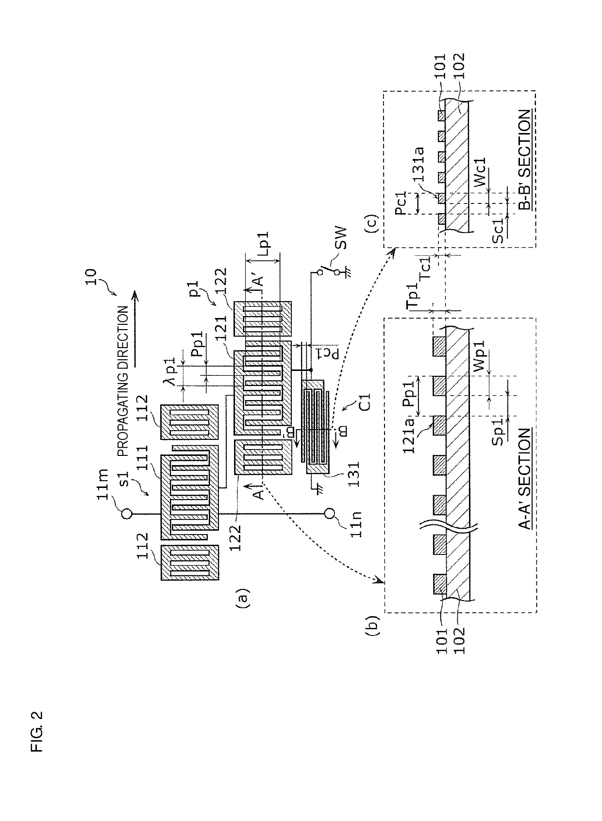
[0104]As shown in FIG. 1A, the filter 10 includes a series arm resonator s1, a parallel arm resonator p1, an interdigital capacitor C1, and a switch SW.
[0105]The series arm resonator s1 is connected between an input-output terminal 11m (first input-output terminal) and an input-output terminal 1...
fourth modified example
of First Preferred Embodiment
[0208]In the second modified example of the first preferred embodiment, the filter 10B includes the variable frequency circuit 11 connected in series with only the parallel arm resonator p1 of the parallel arm resonators p1 and p2. In the third modified example of the first preferred embodiment, the filter 10C includes the variable frequency circuit 11 connected in series with only the parallel arm resonator p2 of the parallel arm resonators p1 and p2. However, a filter may include both of the variable frequency circuit 11 in the second modified example and that in the third modified example.
[0209]FIG. 10A is a circuit diagram of a filter 10D according to a fourth modified example of the first preferred embodiment.
[0210]The filter 10D shown in FIG. 10A preferably includes both of a variable frequency circuit 11a corresponding to the variable frequency circuit 11 of the filter 10B shown in FIG. 8A and a variable frequency circuit 11b corresponding to the ...
fifth modified example
of First Preferred Embodiment
[0220]In the second modified example of the first preferred embodiment, the variable frequency circuit 11 is connected in series with only the parallel arm resonator p1 of the parallel arm resonators p1 and p2. In the third modified example of the first preferred embodiment, the variable frequency circuit 11 is connected in series with only the parallel arm resonator p2 of the parallel arm resonators p1 and p2. However, the variable frequency circuit 11 may be connected in series with a parallel circuit of the parallel arm resonators p1 and p2.
[0221]FIG. 11A is a circuit diagram of a filter 10E according to a fifth modified example of the first preferred embodiment.
[0222]The filter 10E shown in FIG. 11A preferably includes a parallel arm resonance circuit 21E including a variable frequency circuit 11 connected in series with a parallel circuit of the parallel arm resonators p1 and p2.
[0223]In this modified example, the electrode finger pitch of the inter...
PUM
 Abstract
Description
Claims
Application Information
 - R&D
- Intellectual Property
- Life Sciences
- Materials
- Tech Scout
- Unparalleled Data Quality
- Higher Quality Content
- 60% Fewer Hallucinations
Browse by: Latest US Patents, China's latest patents, Technical Efficacy Thesaurus, Application Domain, Technology Topic, Popular Technical Reports.
© 2025 PatSnap. All rights reserved.Legal|Privacy policy|Modern Slavery Act Transparency Statement|Sitemap|About US| Contact US: help@patsnap.com


