
Control System And Method

a control system and control method technology, applied in the direction of electromagnetic radiation sensing, instruments, broadcast service distribution, etc., can solve the problems of not offering any advantage, difficult to immediately learn of the accident, and difficult for managers to know where workers are, so as to prevent additional accidents, prevent additional accidents, and expand and comprehensive industrial safety control

Active Publication Date: 2019-06-13
SUNTECH POWER
View PDF2 Cites 4 Cited by
  • Summary
  • Abstract
  • Description
  • Claims
  • Application Information

AI Technical Summary

Benefits of technology

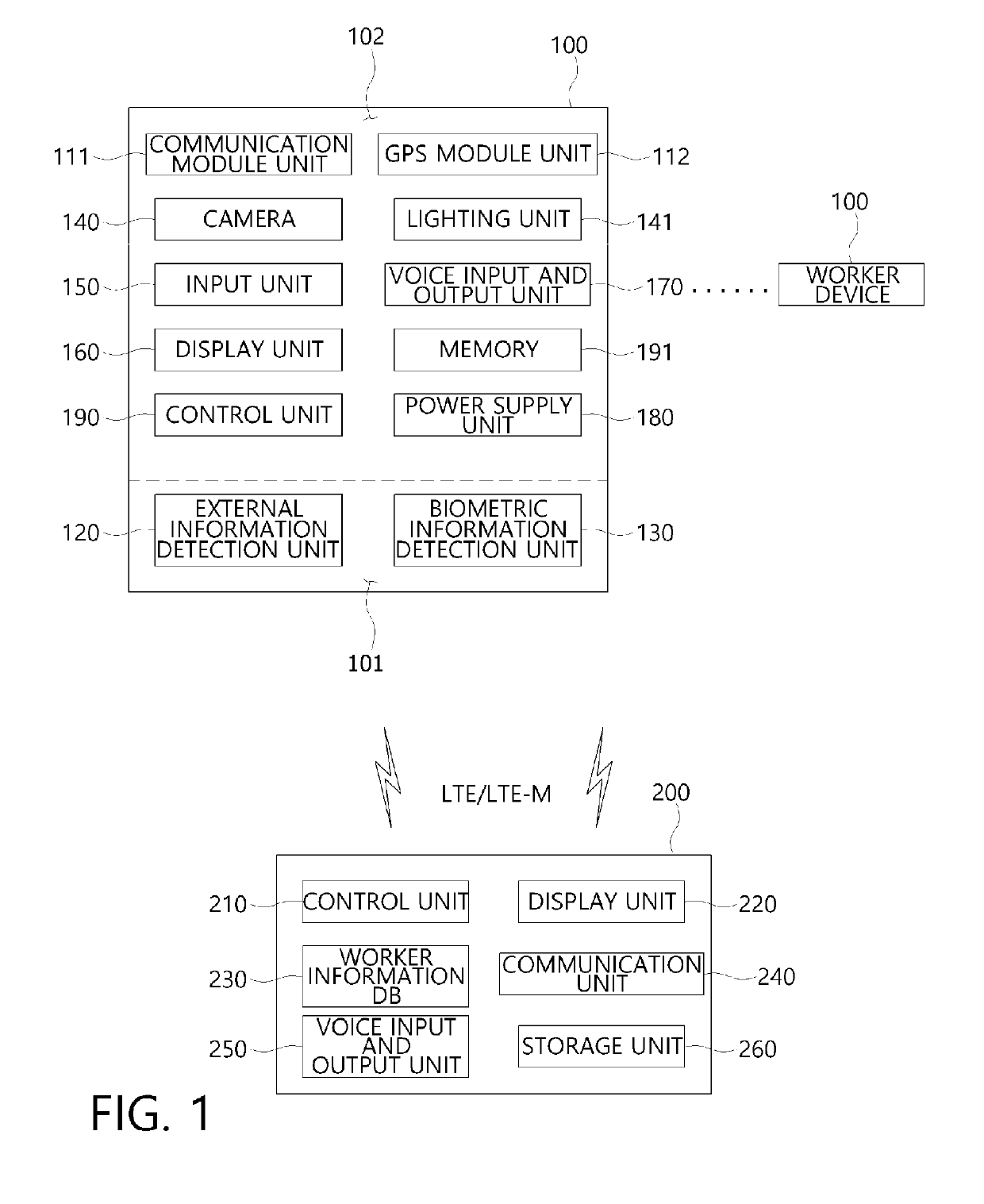
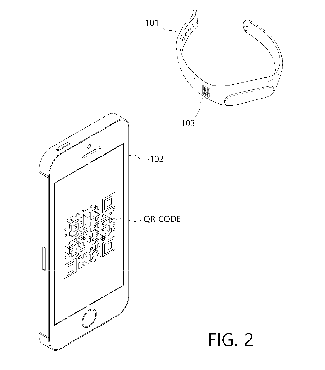
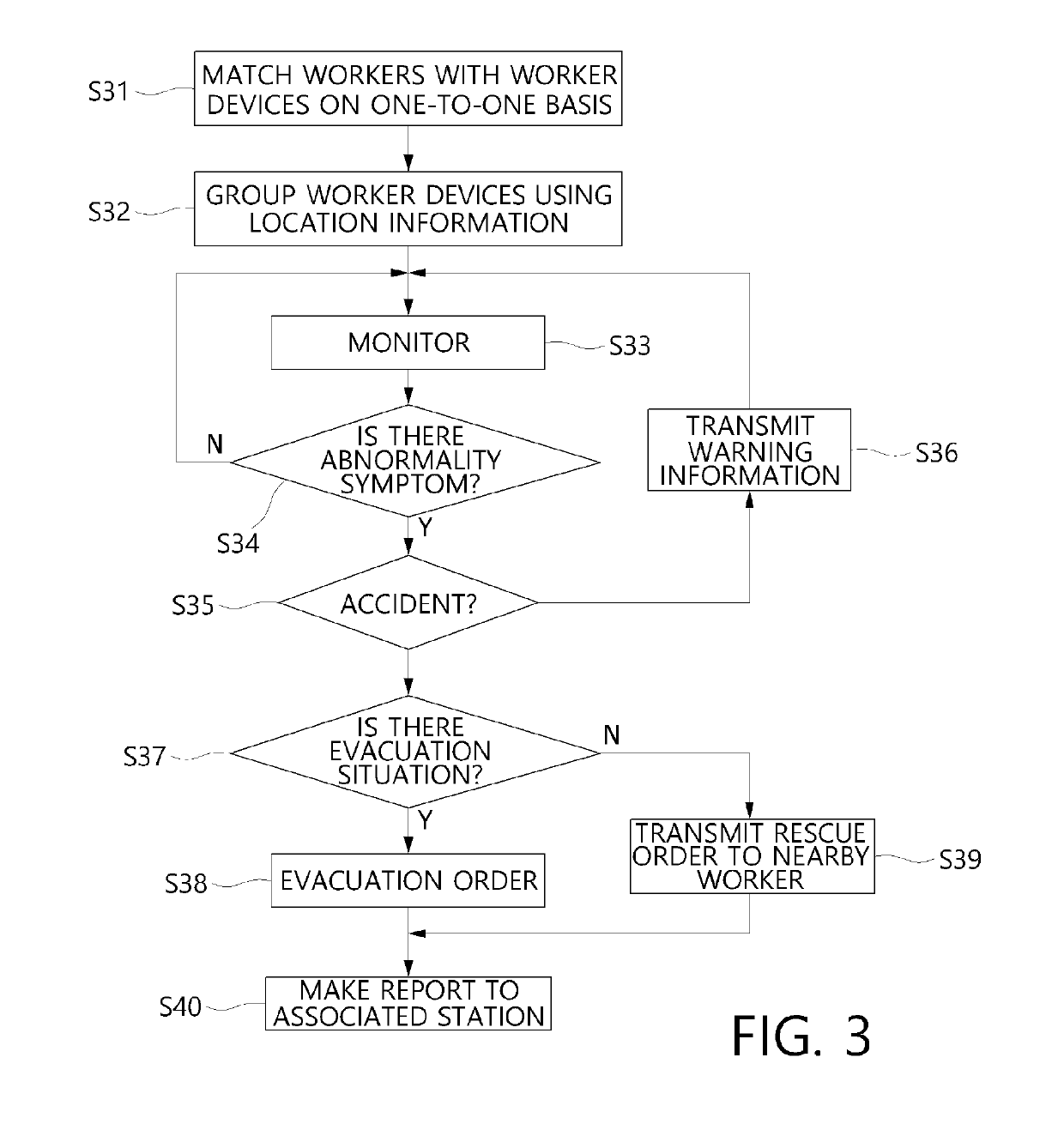
The present invention provides a control system and method for industrial safety that can reduce accidents and prevent additional accidents. The system uses biometric information, location information, and surrounding environment information of workers to analyze and determine if there is a need to rescue or evacuate workers. The system matches workers and their devices on a one-to-one basis, making it easy to manage and determine if an accident has occurred. The system also groups workers within a set range to improve management and easily determine the range of an accident.

Problems solved by technology

Generally, in large-scale industrial sites such as large-scale industrial plant and large-scale construction sites, it is difficult for managers to know where workers are, and even when an accident of a worker who works alone occurs, it is difficult to immediately learn of occurrence of the accident.
However, the published patent enables a worker to obtain situation information on surroundings and thus does not offer any advantage from an ordinary situation because there is no means for directly sensing an accident of a worker and a manager cannot perceive an accident which occurs separately from a surrounding situation.
However, when an accident occurs to a worker, it is not possible to let others know about the accident, and it is not easy to rapidly rescue the worker because an accurate location of the worker is not available.
Also, since a worker's status is determined by collecting a biometric signal regardless of characteristics of the worker's disease or unique biometric information, an error may occur, and it is difficult to manage worker devices worn by workers.

Method used


Image

  • Control System And Method
  • Control System And Method
  • Control System And Method

Examples


Embodiment Construction

[0047]Hereinafter, a control system and method of the present invention will be described in detail with reference to the accompanying drawings.

[0048]Embodiments of the present invention are provided to describe the invention more fully to those of ordinary skill in the art. Embodiments described below may be modified in different forms, and the scope of the present invention is not limited thereto. Rather, these embodiments are provided so that the present invention will be thorough and complete and will fully convey the spirit of the invention to those of ordinary skill in the art.

[0049]Terms used herein are intended to describe particular embodiments and are not intended to limit the scope of the present invention. Unless the context clearly indicates otherwise, a singular form may include a plural form. As used herein, the terms “comprise” and / or “comprising” specify presence of mentioned shapes, numbers, steps, operations, members, elements, and / or groups thereof, but do not ex...


PUM


Abstract

The present invention relates to a control system and method. The control system includes worker devices worn by workers to detect and transmit location information, external information, and biometric information and a control server checking the external information and the biometric information detected by the worker devices and determining whether an accident has occurred. The control server selectively transmits an evacuation or rescue order to worker devices around an accident location according to a cause and a range of the accident.

Description

TECHNICAL FIELD[0001]The present invention relates to a control system and method, and more particularly, to a control system and method for sensing whether an accident has occurred by acquiring user-specific biometric data, and coping with the accident.BACKGROUND ART[0002]Generally, in large-scale industrial sites such as large-scale industrial plant and large-scale construction sites, it is difficult for managers to know where workers are, and even when an accident of a worker who works alone occurs, it is difficult to immediately learn of occurrence of the accident.[0003]To solve this problem, Korean Patent Publication No. 10-2011-0109621 (“Safety Management System and Method Thereof” published on Oct. 6, 2011) has suggested a safety management system whose devices for processing workers' personal information and location information are carried. The safety management system receives sensor information on surrounding environments detected by middleware and provides surrounding en...

Claims


Application Information

Patent Timeline
Patent Type & Authority Applications(United States)
IPC IPC(8): G08B27/00H04W4/02G06K19/06G06K7/14
CPCG08B27/006H04W4/023G06K19/06037G06K7/1417H04W4/025H04W4/08G06Q50/04G06Q10/0637Y02P90/30G06Q50/10G06Q10/0635G06Q50/265
Inventor HAN, BYONG SAM
Owner SUNTECH POWER
Learn More