
Pin Conduction Detection System For Connector Slot Of Circuit Board, And Method Thereof

a technology of conduction detection and connector slot, which is applied in the field of detection system, can solve the problems of insufficient ports provided by the tap controller, affecting test efficiency and test coverage, and achieve the effect of improving test efficiency and coverage ra

Inactive Publication Date: 2019-06-13
INVENTEC PUDONG TECH CORPOARTION +1
View PDF0 Cites 3 Cited by
  • Summary
  • Abstract
  • Description
  • Claims
  • Application Information

AI Technical Summary

Benefits of technology

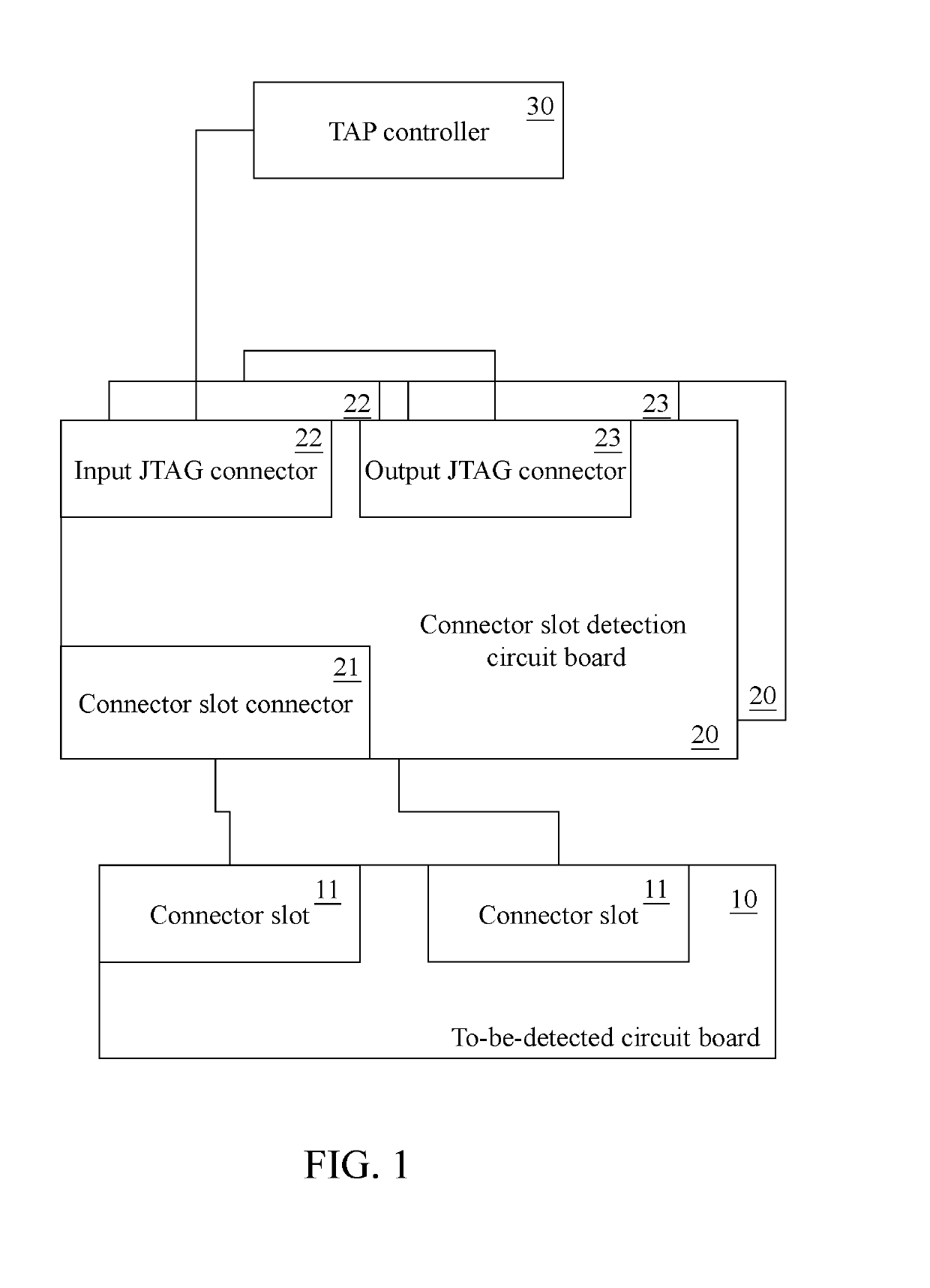
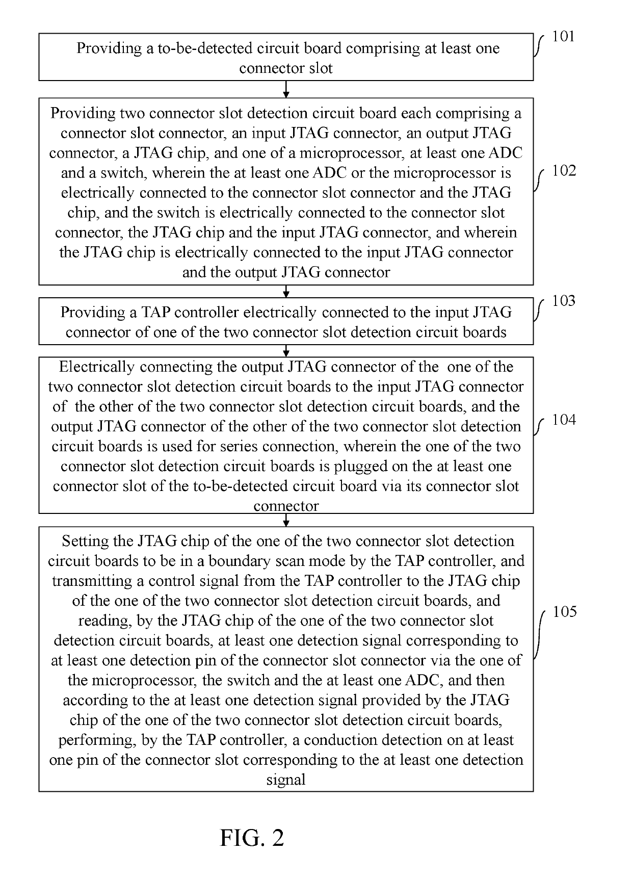
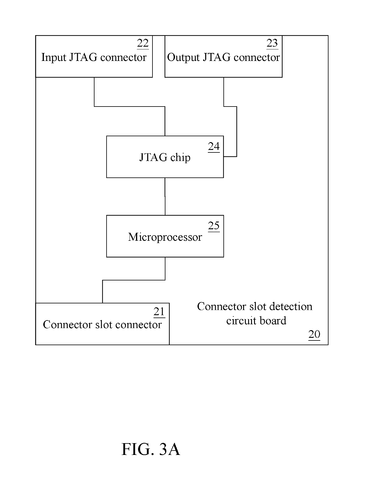
The present invention relates to a system and method for detecting the presence of connection pins on a circuit board. The technology is different from conventional methods because it involves a connector slot detection circuit board that is plugged into the connector slot of the circuit board to be tested. This circuit board is designed with different types of connector slots and can be used to test various types of circuit boards. The system includes a TAP controller that can set the testing circuit in boundary scan mode and read detection signals from pins on the connector slot via an Analog-to-Digital Converter (ADC) and a microprocessor. The TAP controller can then perform a conduction detection on the pins corresponding to the detection signals. The technical effect of this technology is improved efficiency and coverage rate for testing connectors on circuit boards.

Problems solved by technology

However, since a test access port (TAP) controller can provide a limited number of test ports, when the connector slot detection circuit boards including different types of connector slots test the to-be-detected connector slots corresponding thereto, the test ports provided by the TAP controller may be insufficient for above-mentioned test, and it affects test efficiency and the test coverage.

Method used


Image

  • Pin Conduction Detection System For Connector Slot Of Circuit Board, And Method Thereof
  • Pin Conduction Detection System For Connector Slot Of Circuit Board, And Method Thereof
  • Pin Conduction Detection System For Connector Slot Of Circuit Board, And Method Thereof

Examples


Embodiment Construction

[0019]The following embodiments of the present disclosure are herein described in detail with reference to the accompanying drawings. These drawings show specific examples of the embodiments of the present disclosure. It is to be understood that these embodiments are exemplary implementations and are not to be construed as limiting the scope of the present disclosure in any way. Further modifications to the disclosed embodiments, as well as other embodiments, are also included within the scope of the appended claims. These embodiments are provided so that this disclosure is thorough and complete, and fully conveys the inventive concept to those skilled in the art. Regarding the drawings, the relative proportions and ratios of elements in the drawings may be exaggerated or diminished in size for the sake of clarity and convenience. Such arbitrary proportions are only illustrative and not limiting in any way. The same reference numbers are used in the drawings and description to refer...


PUM


Abstract

A pin conduction detection system for connector slot of circuit board, and a method thereof are disclosed. A connector slot detection circuit board is plugged on a connector slot of a to-be-detected circuit board, and the connector slot detection circuit boards including different types of connector slots are concatenated with each other. A TAP controller can set a JTAG chip of the connector slot detection circuit board to be in a boundary scan mode, and the JTAG chip can read at least one detection signal corresponding to at least one detection pin of the connector slot connector via one of a ADC, a microprocessor, and a switch, so that the TAP controller can perform an conduction detection on the pin of the connector slot corresponding to the detection signal. As a result, test efficiency and coverage rate of testing the connector slot of the circuit board can be improved.

Description

CROSS-REFERENCE TO RELATED APPLICATION[0001]This application claims the benefit of Chinese Patent Application No. 201711292332.1, filed Dec. 8, 2017.BACKGROUND OF THE INVENTION1. Field of the Invention[0002]The present invention generally relates to a detection system and a method thereof, more particularly to a system capable of detecting conduction of different types of connector slots concatenated with each other, and a method thereof.2. Description of the Related Art[0003]The conventional manner of detecting conduction of a slot on a circuit board is to plug a specific test circuit board on a to-be-detected connector slot corresponding thereto, for example, a DIMM test circuit board is plugged on a DIMM slot, a PCI-E test circuit board is plugged on a PCI-E slot, and so on. The test circuit board detects conduction of the slot on the circuit board through a boundary scan technology.[0004]However, the test circuit boards corresponding to different connector slots are different in...

Claims


Application Information

Patent Timeline
Patent Type & Authority Applications(United States)
IPC IPC(8): G01R31/3187
CPCG01R31/3187G01R31/31855G01R31/68
Inventor MU, CHANG-QING
Owner INVENTEC PUDONG TECH CORPOARTION
Learn More