Railway fastener for use with crossties

a technology for railway fasteners and crossties, which is applied in the direction of railway fastening, railway construction, roads, etc., can solve the problems of increased wear and tear of the crosstie, increased installation difficulty, and increased installation time, so as to improve the efficiency of installation and improve the effect of railway fastening of crossties

Active Publication Date: 2019-06-13
PANDROL LTD
View PDF0 Cites 0 Cited by
  • Summary
  • Abstract
  • Description
  • Claims
  • Application Information

AI Technical Summary

Benefits of technology

[0007]It is an objective of the present invention to improve railway fastening of crossties to support structures, such as steel girder beams and in turn prevent the crosstie from movement.
[0008]It is another objective of the present intention to improve occupational safety for the installation of crossties on structures and increase the efficiency of the installation of crossties on supporting structures.

Problems solved by technology

The support must be mounted below the crosstie and, therefore, is difficult and time consuming to install.
Moreover, over time, the vertical bolt weakens the crosstie, increases wear and tear of the crosstie and the head of the clip poses a tripping hazard.
Additionally, because the clip is disposed under the tie, it is difficult to determine when the clip is properly positioned during installation, or whether the clip has been corroded by extensive wear and tear and exposure to extreme weather conditions and, as a result, needs to be replaced.
There are similar problems with U.S. Pat. No. 3,552,649 to Burnwell.
Again, the spikes weaken the crossties and the horizontal bar and bolt extend above the crossties and as a result, present a tripping hazard.
Moreover the system is difficult to install correctly.

Method used


Image

  • Railway fastener for use with crossties
  • Railway fastener for use with crossties
  • Railway fastener for use with crossties

Examples


Embodiment Construction

[0019]With reference to the drawings, wherein the same reference number indicates the same element throughout, exemplary embodiments of a railway fastener will be described.

[0020]As described above, FIG. 1 illustrates a known rail seat assembly 10 that includes a rail 12 that includes a web 16 and flanges 18 seated on a tie plate 20 that is secured to a crosstie 14. The rail 12 is secured to the crosstie 14 by clips 22 that are engage the flanges 18 of the rail 12.

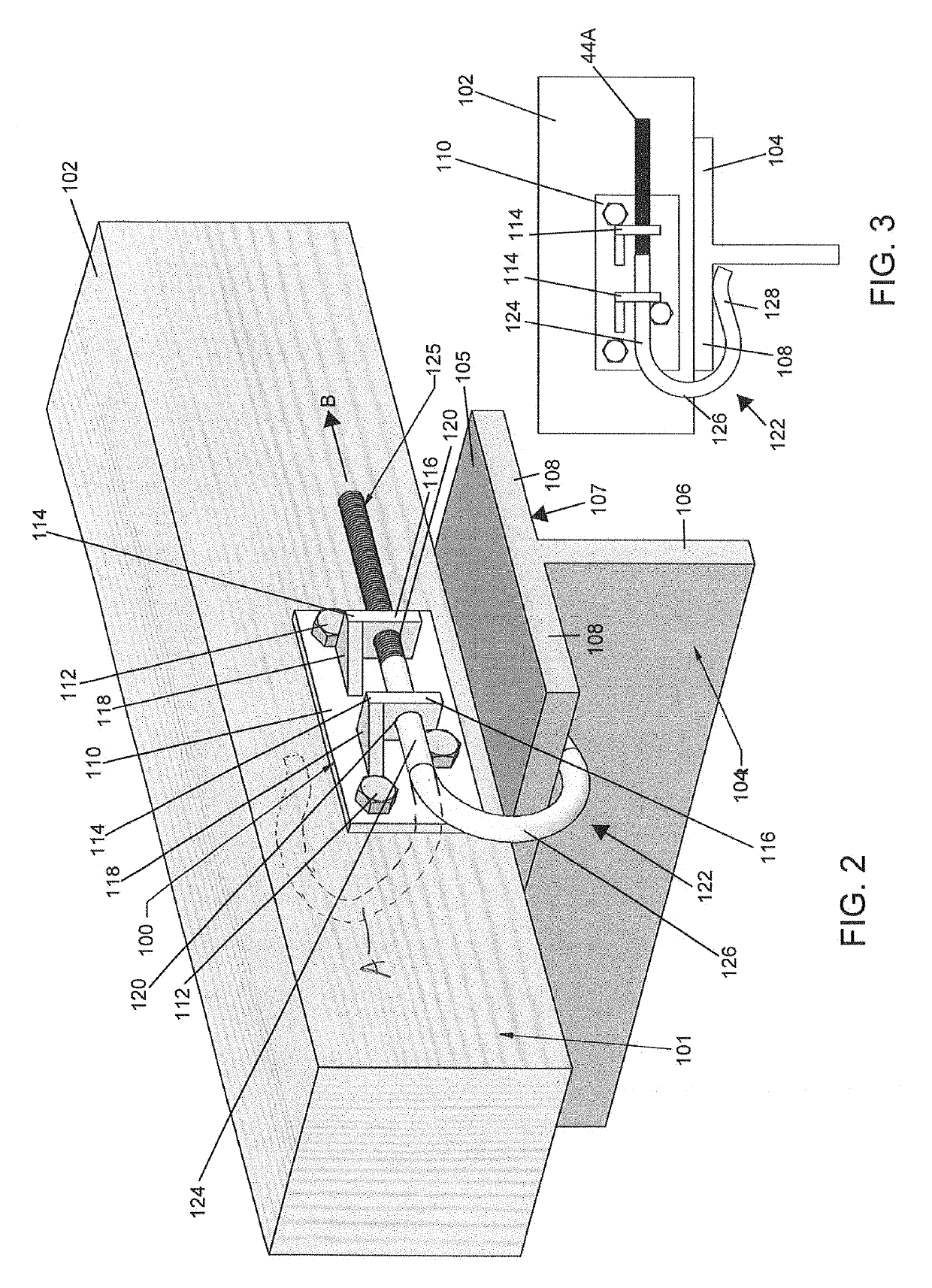
[0021]FIGS. 2 and 3 show a crosstie 102 secured to a steel portion or girder 104 of a structure, such as an elevated bridge, by a railroad fastening system 100 according to an exemplary embodiment of the prevent invention. The crosstie 102 supports at least a pair of rails (not shown) using, for example, the rail seat assembly 10 that is illustrated in FIG. 1 and described above. However, the rail seat assembly 10 and / or another support assembly have been omitted in FIG. 2 for the sake of clarity. The girder 104 includes a...


PUM


Abstract

A fastening system configured to attach railroad crossties to one or more support structures such as the girder of a bridge. The fastening system includes a plate mounted on a crosstie and a clip attached to the plate that is configured to provide a force between the support structure and the crosstie and secure the crosstie in place

Description

CROSS-REFERENCE TO RELATED APPLICATION[0001]This application claims priority to U.S. Provisional Patent Application No. 62 / 597,576, filed Dec. 12, 2017, which is hereby incorporated by reference in its entirety as part of the present disclosure.FIELD OF THE INVENTION[0002]This disclosure relates generally to railroad systems and more specifically to railway fastening systems for use with crossties when fastened to steel structures such as bridges having girders.BACKGROUND OF THE INVENTION[0003]In conventional railroad systems, rails are supported on crossties using rail support assemblies. One such assembly is shown and described in commonly assigned U.S. Pat. No. 4,561,589 to Hixson. As shown in FIG. 1, a rail seat assembly 10 supports a rail 12 on a wooden crosstie 14. The rail 10 includes a web 16 and flanges 18. The rail seat assembly 10 includes a tie plate 20 that is seated on the crosstie 14 and supports two clips 22 that each engages one of the flanges 18 of rail 12.[0004]Co...

Claims


Application Information

Patent Timeline
Patent Type & Authority Applications(United States)
IPC IPC(8): E01D19/12E01B26/00
CPCE01D19/12E01B26/00E01B2201/02E01B3/00
Inventor FAZIO, ANTHONY
Owner PANDROL LTD
Why Eureka
Try Eureka