
Vibrating device, camera water-droplet-removing device, and camera

Active Publication Date: 2019-06-13
MURATA MFG CO LTD
View PDF0 Cites 4 Cited by
  • Summary
  • Abstract
  • Description
  • Claims
  • Application Information

AI Technical Summary

Benefits of technology

The present invention provides vibrating devices that will not put a lot of pressure on a piezoelectric vibrator or cause a heavy load on a camera when removing water droplets or other substances that stick to its surface. These vibrating devices have multiple piezoelectric vibrators on its sides, which makes it easy to create vibrations in different modes. With these devices, water droplets or other substances can be easily removed without causing excessive stress on the vibrator.

Problems solved by technology

Vehicle-mounted cameras and cameras installed outdoors are exposed to rain.
However, water droplets that have adhered to the cover may reduce the clarity of the view of the camera and hinder accurate image capture.
Accordingly, the piezoelectric ceramic vibrator or the ultrasonic transducer receives large stress, and cracks may be formed therein as a result of use over time.
This may lead to malfunction of the piezoelectric ceramic vibrator or the ultrasonic transducer.

Method used


Image

  • Vibrating device, camera water-droplet-removing device, and camera
  • Vibrating device, camera water-droplet-removing device, and camera
  • Vibrating device, camera water-droplet-removing device, and camera

Examples


Embodiment Construction

[0039]Preferred embodiments of the present invention will be described below with reference to the accompanying drawings.

[0040]It is to be noted that each of the preferred embodiments described in this specification is illustrative, and partial replacements and combinations of the structures of different preferred embodiments are possible.

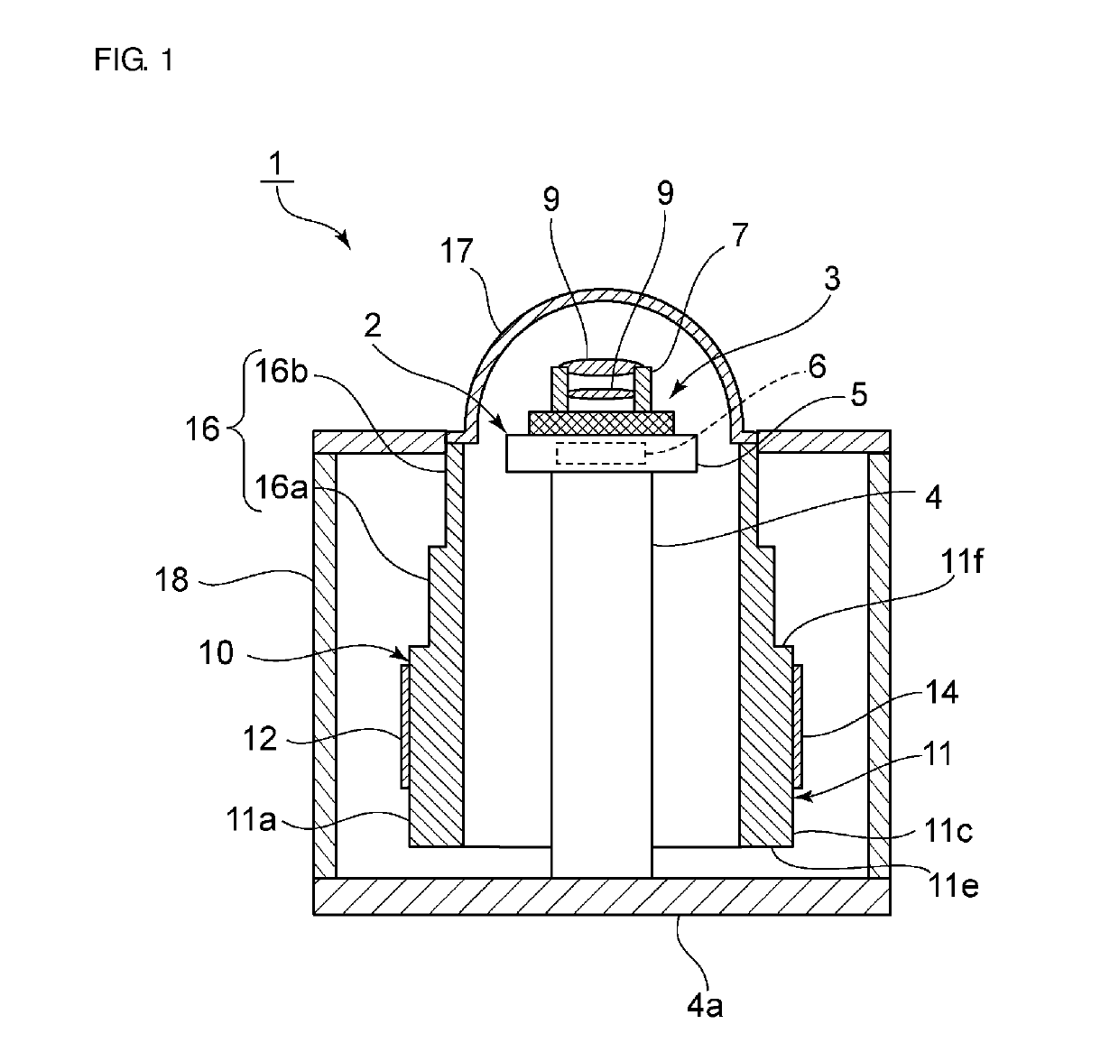
[0041]FIG. 1 is a front sectional view of a camera according to a first preferred embodiment of the present invention. FIG. 2A is a perspective view of a main portion of a vibrating device from which a light transmitting body unit is removed. FIG. 2B is a plan view of the main portion. FIG. 3 is a partially cutaway sectional perspective view of the main portion.

[0042]A camera 1 includes a camera water-droplet-removing device 2. The camera water-droplet-removing device 2 includes a camera main body 3. It is not necessary that the entirety of the camera main body 3 be contained in the camera water-droplet-removing device 2 as long as at least a porti...


PUM


Abstract

A vibrating device includes a tubular body including a first end, a second end, and a plurality of side surfaces that connect the first and second ends, piezoelectric vibrators that are fixed to the tubular body and vibrate the tubular body, and a light transmitting body unit that is directly or indirectly connected to the second end of the tubular body.

Description

CROSS REFERENCE TO RELATED APPLICATIONS[0001]This application claims the benefit of priority to Japanese Patent Application No. 2016-232611 filed on Nov. 30, 2016 and is a Continuation Application of PCT Application No. PCT / JP2017 / 026887 filed on Jul. 25, 2017. The entire contents of each application are hereby incorporated herein by reference.BACKGROUND OF THE INVENTION[0002]1. Field of the Invention[0003]The present invention relates to a vibrating device including a piezoelectric vibrator and a tubular body, a camera water-droplet-removing device including the vibrating device, and a camera.[0004]2. Description of the Related Art[0005]Vehicle-mounted cameras and cameras installed outdoors are exposed to rain. Accordingly, a cover made of glass or transparent plastic is placed in front of a lens. However, water droplets that have adhered to the cover may reduce the clarity of the view of the camera and hinder accurate image capture.[0006]Japanese Unexamined Patent Application Publ...

Claims


Application Information

Patent Timeline
IPC IPC(8): B06B1/06G03B15/00G03B17/08H04N5/225G03B17/56G02B7/02G02B27/00
CPCB06B1/06G03B15/00G03B17/08H04N5/225G03B17/56G02B7/02G02B27/0006G03B17/02B06B1/0607G02B7/021H04N23/52H04N23/55B60S1/0848H04N23/00
Inventor FUJIMOTO, KATSUMIHORIGUCHI, CHIKAHIRONISHIYAMA, KENJIKURATANI, YASUHIROICHIGUCHI, SHINICHIRO
Owner MURATA MFG CO LTD
Learn More