
Thermal pattern sensor with pyroelectric capacitance and hard protective layer

a technology of pyroelectric capacitance and thermoelectric pattern, applied in the field of thermoelectric pattern sensors, can solve the problems of no longer being able to obtain satisfactory contrast, zero signal obtained, and the inability of sensors to carry out measurements

Active Publication Date: 2019-06-06
COMMISSARIAT A LENERGIE ATOMIQUE ET AUX ENERGIES ALTERNATIVES
View PDF0 Cites 0 Cited by
  • Summary
  • Abstract
  • Description
  • Claims
  • Application Information

AI Technical Summary

Benefits of technology

The patent proposes a thermal pattern sensor with a protective layer that prevents degradation of the sensor due to the conductive portions forming the heating elements. The protective layer prevents the heating elements from piercing the dielectric layer that covers the upper electrode, maintaining the integrity of the pixels of the sensor. The thickness of the protective layer is between around 100 nm and 600 nm. The material of sol-gel type may be obtained from organometallic precursors such as the metal alkoxide of silicon or titanium, found in organic solutions.

Problems solved by technology

However, these sensors have the drawback of carrying out a measurement that depends uniquely on the difference between the temperature of the finger and the temperature of the sensor.
Thus, after several seconds of contact between the finger and the sensor, the temperature of the finger and the temperature of the contact surface are homogenised, and it is no longer possible to obtain a satisfactory contrast.
It may also happen that the level of the signal obtained is zero when the finger and the sensor are at the same temperature, or instead that the contrast of the captured images varies, which then poses problems during the later processing of the images obtained (for example, an inversion of the temperatures leads to an inversion of the image obtained).
Apart from these salient angles, the sensor may also be deteriorated by the roughnesses formed by these electrically conductive portions produced by depositions of conductive inks, this roughness being for example of the order of 1.5 μm RMS and due to the inhomogenities of the depositions as well as the shape of the particles.
When the finger presses on the sensor, the particles of silver and / or the roughnesses of the conductive portion forming the heating element can pierce the dielectric layer on which this conductive portion lies, and thereby damage the pyroelectric capacitance lying under the dielectric layer.
By piercing the dielectric layer, conduction paths may be created between the conductive portions forming the heating elements and the upper electrodes of the pyroelectric capacitances of the pixels, causing considerable leakage currents within the pixels, which prevents the correct operation of the device.
In the case of particles of large sizes, it is even possible to end up with total deterioration of the sensor, making it non-operational.

Method used


Image

  • Thermal pattern sensor with pyroelectric capacitance and hard protective layer

Examples


Embodiment Construction

[0014]There thus exists a need to propose a thermal pattern sensor in which the risks of degradation of the sensor due to the conductive portions forming the heating elements and comprising depositions of electrically conductive particles are reduced or eliminated.

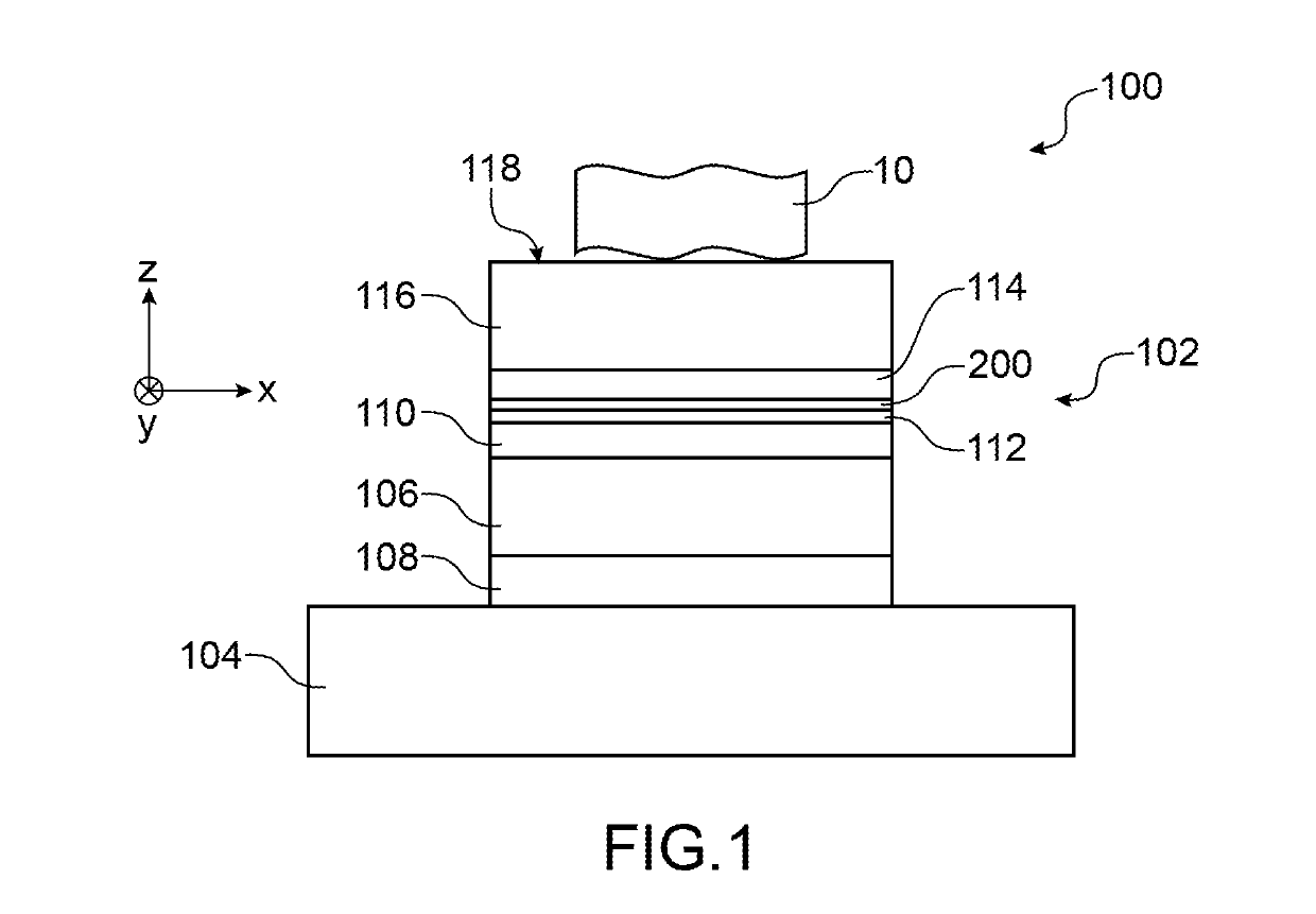
[0015]To do so, a thermal pattern sensor comprising several pixels arranged on a substrate is proposed, each pixel including at least:[0016]a pyroelectric capacitance formed by at least one portion of pyroelectric material arranged between at least one lower electrode and at least one upper electrode, with the lower electrode arranged between the substrate and the portion of pyroelectric material,[0017]a dielectric layer such that the upper electrode is arranged between the portion of pyroelectric material and the dielectric layer,[0018]a heating element including at least one deposition of electrically conductive particles and such that the dielectric layer is arranged between the upper electrode and the heating element,[...


PUM


Abstract

Thermal pattern sensor comprising several pixels arranged on a substrate, each pixel including at least: a pyroelectric capacitance formed by at least one portion of pyroelectric material arranged between at least one lower electrode and at least one upper electrode, with the lower electrode arranged between the substrate and the portion of pyroelectric material, a dielectric layer such that the upper electrode is arranged between the portion of pyroelectric material and the dielectric layer, a heating element including at least one deposition of electrically conductive particles and such that the dielectric layer is arranged between the upper electrode and the heating element, a protective layer arranged between the dielectric layer and the heating element and including at least one material of which the Shore A hardness is greater than or equal to around 60.

Description

TECHNICAL FIELD AND PRIOR ART[0001]The invention relates to a thermal pattern sensor exploiting the pyroelectric properties of a material, and advantageously forming a finger print sensor.[0002]Finger print detection may be carried out by so-called “passive” sensors exploiting a difference in temperature between that of the finger and that of the sensor, as described in the documents U.S. Pat. Nos. 4,394,773, 4,429,413 and 6,289,114. At the ridges of the print, the skin of the finger is in direct physical contact with the sensor. A thermal transfer between the skin and the contact surface of the sensor takes place by conduction, which leads to a first temporal variation in temperature. At the valleys of the print, the skin of the finger is not in direct physical contact with the sensor. A thermal transfer between the skin and the contact surface of the sensor takes place through air, which is rather a heat insulator, which leads to a second temporal variation in temperature, less im...

Claims


Application Information

Patent Timeline
IPC IPC(8): H01L37/02H01L27/16G06K9/00
CPCH01L37/02H01L27/16G06K9/0002H01L37/025G01J5/34G06V40/1329G06V40/1306H10N19/00H10N15/10H10N15/15
Inventor BENWADIH, MOHAMMEDSERBUTOVIEZ, CHRISTOPHE
Owner COMMISSARIAT A LENERGIE ATOMIQUE ET AUX ENERGIES ALTERNATIVES
Learn More