Vehicle body floor structure

a technology for vehicle body and floor, applied in vehicle components, superstructure sub-units, transportation and packaging, etc., can solve the problems of unproposed optimal structure for combining these techniques, resonance and abnormal noise of floor panels, and achieve the effect of sufficiently suppressing vibration of floor panels, enhancing rigidity of floor panels, and reducing vibration of floor panels

Active Publication Date: 2019-06-06
TOYOTA JIDOSHA KK
View PDF5 Cites 3 Cited by
  • Summary
  • Abstract
  • Description
  • Claims
  • Application Information

AI Technical Summary

Benefits of technology

[0007]While setting the resonance frequency of a floor panel higher or damping vibration occurring in a floor panel by a vibration damping material as described above is effective in suppressing generation of the abnormal noise, optimal structure for combining these techniques has not yet been proposed. The inventor of the present disclosure has considered a structure that combines these techniques and can thereby effectively suppress vibration occurring in a floor panel.
[0008]The present disclosure provides a vehicle body floor structure that combines the technique of setting the resonance frequency of a floor panel higher by enhancing the rigidity of the floor panel and the technique of damping vibration occurring in a floor panel by applying a vibration damping material to the floor panel, and that can thereby effectively suppress vibration occurring in the floor panel.
[0010]According to the first aspect, the floor panel is provided with the steps, which allows the resonance frequency of the floor panel to be set higher by enhancing the rigidity of the floor panel. Moreover, the vibration damping material is applied to the surface of the floor panel along at least one outer edge portion of the region of the floor panel surrounded by the vehicle body framework members, among the outer edge portions extending along the long-side direction and the outer edge portions extending along the short-side direction, so that the vibration damping function of the vibration damping material can be effectively exerted. Specifically, the principle of vibration damping by the vibration damping material is that the vibration damping material exerts the damping function by stretching when the floor panel vibrates and deforms. It is the outer edge portions of the region surrounded by the vehicle body framework members that undergo a large change in the curvature of bending deformation in a cross-section of the floor panel while the floor panel is vibrating. These outer edge portions are namely the outer edge portions of the region extending along the long-side direction and the outer edge portions thereof extending along the short-side direction. Therefore, if the vibration damping material has been applied along these outer edge portions (at least one outer edge portion among the outer edge portions), this means that the vibration damping material has been applied to the surface of the portions that undergo a large change in the curvature of bending deformation in a cross-section of the floor panel during vibration of the floor panel, so that the vibration damping function of the vibration damping material can be effectively exerted. Thus, it is possible to sufficiently suppress vibration of the floor panel, while reducing the amount of vibration damping material used compared with when the vibration damping material is applied evenly over the entire floor panel.
[0012]According to the above configuration, the steps of the floor panel having the ridge lines extending along the short-side direction of the region surrounded by the vehicle body framework members are arrayed along the long-side direction of the region. Accordingly, during vibration of the floor panel, a central portion of the step in the short-side direction (the short-side direction of the region) undergoes a relatively small change in the curvature of beading deformation, while portions of the step at both ends in the short-side direction (outer edge portions extending along the long-side direction) undergo a relatively large change in the curvature of bending deformation. Thus, these outer edge portions extending along the long-side direction constitute portions that undergo the largest change in the curvature of bending deformation in a cross-section of the floor panel. According to the solution of the present disclosure, the vibration clamping material is applied to the surface of the floor panel along only these outer edge portions extending along the long-side direction, which means that the vibration damping material is applied to the surfaces of only those portions that undergo the largest change in the curvature of bending deformation in a cross-section of the floor panel. In other words, portions that undergo the largest change in the curvature of bending deformation are proactively created as the floor structure for a vehicle, and the vibration damping material is applied to these portions. Thus, it is possible to sufficiently suppress vibration of the floor panel by exerting a sufficient vibration damping function, while significantly reducing the amount of vibration damping material used.
[0014]According to this configuration, as in the above-described case, a larger amount of vibration damping material is applied to the surface of the portions that undergo a large change in the curvature of bending deformation in a cross-section of the floor panel dating vibration of the floor panel, so that the vibration damping function of the vibration damping material can be effectively exerted. Moreover, the vibration damping material is applied also to the central portion of the region, and thus the vibration damping function of the vibration damping material can be exerted also at the central portion of the region.
[0019]In the present disclosure, the steps having the ridge lines extending along the short-side direction of the region surrounded by the vehicle body framework members are provided in the floor panel so as to be arrayed along the long-side direction of the region, and moreover, the vibration damping material is applied to the surface of the floor panel along the outer edge portions of the region. Thus, the rigidity of the floor panel is enhanced and the resonance frequency of the floor panel can be thereby set higher. Moreover, the vibration damping function of the vibration damping material can be effectively exerted. It is therefore possible to sufficiently suppress vibration of the floor panel, while reducing the amount of vibration damping material used compared with when the vibration damping material is applied evenly over the entire floor panel.

Problems solved by technology

When the vehicle body vibrates as a result of an input from a road surface into the vehicle body, transmission of vibration from the engine, etc., and the frequency of this vibration of the vehicle body matches the resonance frequency of the floor panel, the floor panel resonates and generates abnormal noise (low-frequency solid-borne sound), such as booming noise, giving an uncomfortable feeling to an occupant.
While setting the resonance frequency of a floor panel higher or damping vibration occurring in a floor panel by a vibration damping material as described above is effective in suppressing generation of the abnormal noise, optimal structure for combining these techniques has not yet been proposed.

Method used


Image

  • Vehicle body floor structure
  • Vehicle body floor structure
  • Vehicle body floor structure

Examples


example of experiment

[0066]Next, an example of experiment that was conducted to confirm the above effects Will be described.

[0067]In this example of experiment, vibration of a resonance frequency was induced in each of the floor panel 1 according to the embodiment and a floor panel according to a comparative example (a floor panel of which substantially the entire upper surface is evenly coated with a vibration damping material), and the sound pressure sensitivity in each frequency band was measured.

[0068]FIG. 10 is a graph showing the result of this vibration experiment. The solid line in FIG. 10 shows the measurement result of the sound pressure sensitivity in each frequency band of the floor panel 1 according to the embodiment. The dashed line in FIG. 10 shows the measurement result of the sound pressure sensitivity in each frequency band of the floor panel according to the comparative example.

[0069]As is clear from FIG. 10, the floor panel 1 according to the embodiment bias lower sound pressure sens...

modified example 1

[0070]Next, Modified Example 1 will be described. This modified example is different from the embodiment in the coating regions of the vibration damping material 9. The structure is otherwise the same as in the embodiment, and therefore only the coating regions of the vibration damping material 9 will be described here.

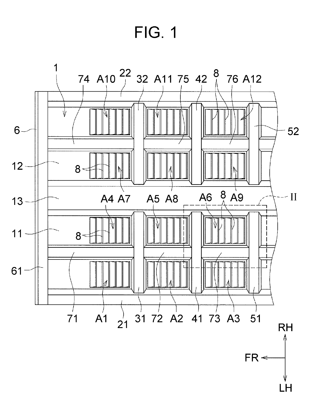
[0071]FIG. 11 is a view corresponding to FIG. 1, showing the coating regions of the vibration damping material 9 in the floor panel 1 according to this modified example. As shown in FIG. 11, in this modified example, the surface of the floor panel 1 is coated with the vibration damping material 9 along only the outer edge portions extending along the long-side direction of the regions A1 to A12 of the floor panel 1 surrounded by the vehicle body framework members. Also in this modified example, among the outer edge portions of the regions A1 to A12 extending along the long-side direction, those regions in which a projection protruding upward from the floor panel 1, an...

modified example 2

[0075]Next, Modified Example 2 will be described. This modified example is also different from the embodiment in the coating regions of the vibration damping material 9. As the structure is otherwise the same as in the embodiment, only the coating regions of the vibration damping material 9 will be described here.

[0076]In this modified example, as in the above embodiment, the floor panel 1 is coated with the vibration damping material 9 along each of the outer edge portions extending along the long-side direction and the outer edge portions extending along the short-side direction of the regions A1 to A12 surrounded by the vehicle body framework members. In addition, the central portions of the regions A1 to A12 are also coated with the vibration damping material 9, The amount of coating of the vibration damping material 9 (the thickness dimension of the coating of the vibration damping material 9) at the central portions of the regions A1 to A12 is set to be smaller than the amount...


PUM


Abstract

A vehicle body floor structure includes: a plurality of first vehicle body framework members extending along a vehicle body front-rear direction; a plurality of second vehicle body framework members extending along a vehicle width direction; a floor panel to which each of the first vehicle body framework members and the second vehicle body framework members is joined; and a vibration damping material that is applied to a surface of the floor panel. The floor panel includes a plurality of steps having ridge lines extending along a short-side direction of a first region. The first region is surrounded by the first vehicle body framework members and the second vehicle body framework members. The vibration damping material is applied along at least one outer edge portion of the first region.

Description

CROSS-REFERENCE TO RELATED APPLICATIONS[0001]This application claims priority to Japanese Patent Application No. 2017-233165 filed on Dec. 5, 2017, which is incorporated herein by reference in its entirety including the specification, drawings and abstract.BACKGROUND1. Technical Field[0002]The present disclosure relates to a vehicle body floor structure. More particularly, the present disclosure relates to a measure tor suppressing vibration occurring in a floor panel.2. Description of Related Art[0003]As disclosed in Japanese Patent Application Publication No. 2909-286249 (JP 2009-286249 A), a floor panel of a vehicle body has welded thereon vehicle body framework members, such as frames extending along a vehicle body front-rear direction and cross members extending along a vehicle width direction.[0004]When the vehicle body vibrates as a result of an input from a road surface into the vehicle body, transmission of vibration from the engine, etc., and the frequency of this vibratio...

Claims


Application Information

Patent Timeline
Patent Type & Authority Applications(United States)
IPC IPC(8): B60R13/08B62D25/20
CPCB60R13/083B62D25/20
Inventor SHIGIHARA, TAKAYOSHI
Owner TOYOTA JIDOSHA KK
Why Eureka
Try Eureka