
LED unit for display and display apparatus having the same

Active Publication Date: 2019-05-30
SEOUL VIOSYS CO LTD
View PDF2 Cites 14 Cited by
  • Summary
  • Abstract
  • Description
  • Claims
  • Application Information

AI Technical Summary

Benefits of technology

This patent describes a new light emitting diode (LED) technology for displays. The invention reduces the time it takes to mount the LEDs and makes them more robust. The LEDs are constructed using a growth substrate, which strengthens them. The invention also includes electrode pads that prevent the LEDs from peeling off during manufacture or use. Overall, this new technology improves the manufacturing process and reliability of LED displays.

Problems solved by technology

However, when one LED chip forms each subpixel, the number of LED chips required to form a display apparatus can exceed millions, thereby causing excessive time consumption for a mounting process.
However, such would cause deterioration in brightness from reduced luminous area.

Method used


Image

  • LED unit for display and display apparatus having the same
  • LED unit for display and display apparatus having the same
  • LED unit for display and display apparatus having the same

Examples


Embodiment Construction

[0171]In the following description, for the purposes of explanation, numerous specific details are set forth in order to provide a thorough understanding of various exemplary embodiments or implementations of the invention. As used herein “embodiments” and “implementations” are interchangeable words that are non-limiting examples of devices or methods employing one or more of the inventive concepts disclosed herein. It is apparent, however, that various exemplary embodiments may be practiced without these specific details or with one or more equivalent arrangements. In other instances, well-known structures and devices are shown in block diagram form in order to avoid unnecessarily obscuring various exemplary embodiments. Further, various exemplary embodiments may be different, but do not have to be exclusive. For example, specific shapes, configurations, and characteristics of an exemplary embodiment may be used or implemented in another exemplary embodiment without departing from ...


PUM


Abstract

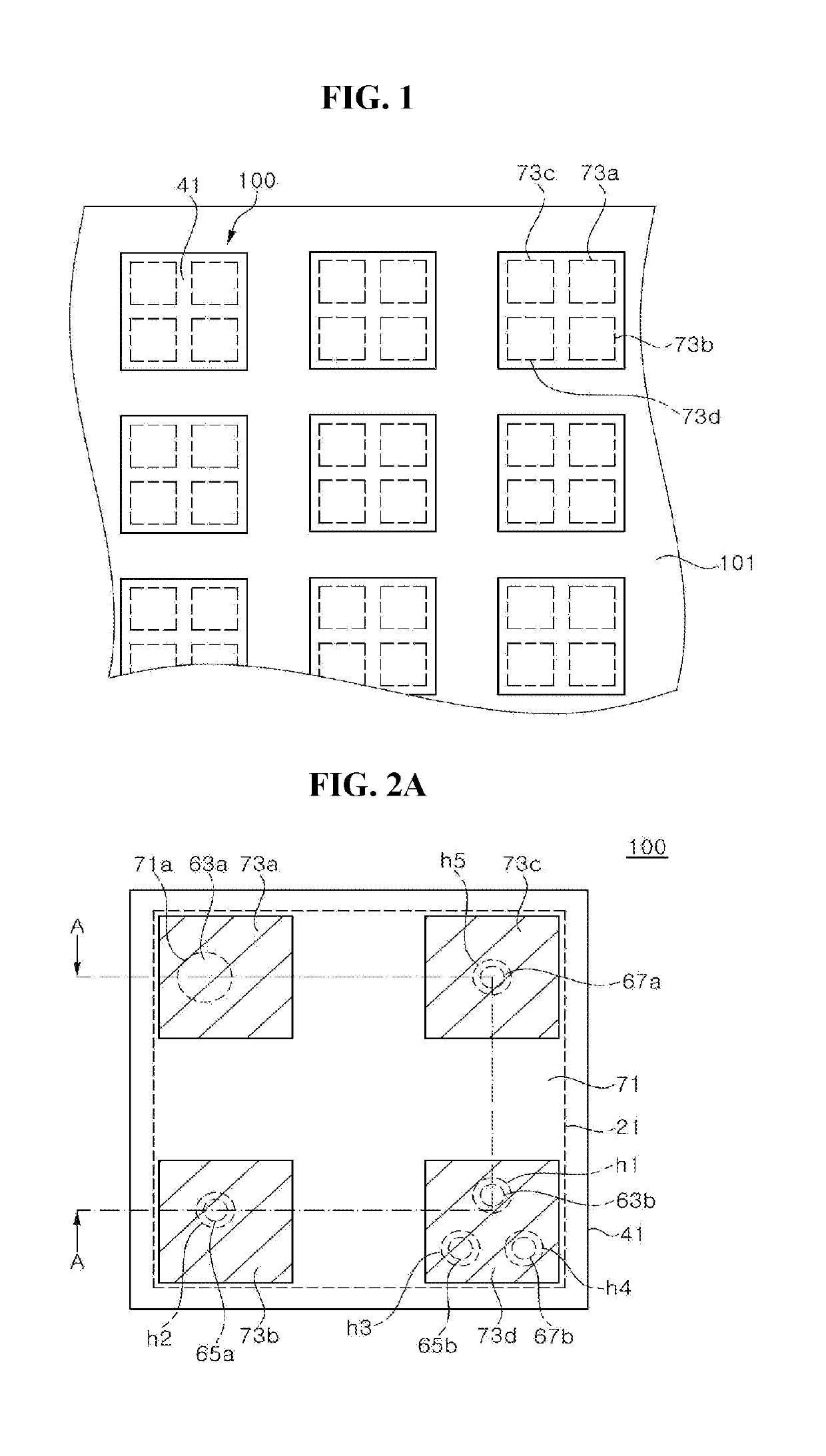
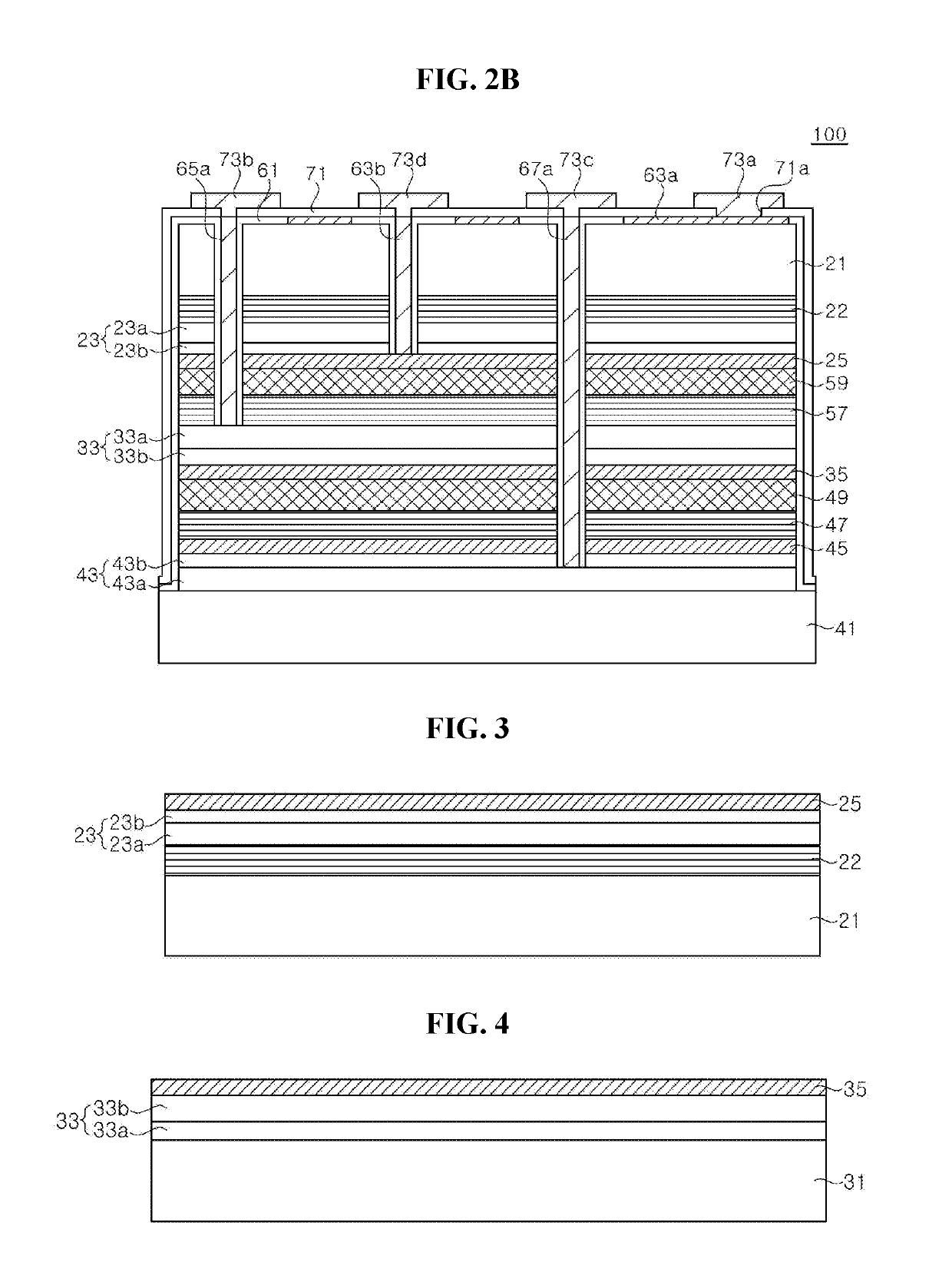
A light emitting device for a display including a first substrate, a first LED sub-unit disposed on the first substrate, a second LED sub-unit disposed on the first LED sub-unit, a third LED sub-unit disposed on the second LED sub-unit, a second substrate disposed on the third LED sub-unit, a first electrode pad, a second electrode pad, a third electrode pad, and a fourth electrode pad disposed on the second substrate, and through-hole vias electrically connecting the second, third, and fourth electrode pads to the first, second, and third LED sub-units, respectively, in which the first electrode pad is electrically connected to the first LED sub-unit without overlapping any through-hole vias.

Description

CROSS REFERENCE TO RELATED APPLICATIONS[0001]This application claims priority from and the benefit of the U.S. Provisional Patent Application No. 62 / 590,870, filed on Nov. 27, 2017, U.S. Provisional Patent Application No. 62 / 590,854, filed on Nov. 27, 2017, U.S. Provisional Patent Application No. 62 / 608,297, filed on Dec. 20, 2017, U.S. Provisional Patent Application No. 62 / 614,900, filed on Jan. 8, 2018, U.S. Provisional Patent Application No. 62 / 635,284, filed on Feb. 26, 2018, U.S. Provisional Patent Application No. 62 / 643,563, filed on Mar. 15, 2018, United States Provisional Patent Application No. 62 / 657,589, filed on Apr. 13, 2018, U.S. Provisional Patent Application No. 62 / 657,607, filed on Apr. 13, 2018, U.S. Provisional Patent Application No. 62 / 683,564, filed on Jun. 11, 2018, the disclosures of which are hereby incorporated by reference for all purposes as if fully set forth herein.BACKGROUNDField[0002]Exemplary implementations of the invention relate generally to a light...

Claims


Application Information

Patent Timeline
IPC IPC(8): H01L25/13H01L33/62H01L33/38
CPCH01L25/13H01L33/62H01L33/38H01L27/156H01L25/0753H01L25/0756H01L33/0093H01L33/382H01L22/20
Inventor CHAE, JONG HYEONLEE, CHUNG HOONKIM, CHANG YEONJANG, SEONG GYULEE, HO JOONJANG, JONG MIN
Owner SEOUL VIOSYS CO LTD
Learn More