
Method for detecting intrusion

a detection method and intrusion detection technology, applied in the direction of burglar alarm mechanical actuation, optical radiation measurement, instruments, etc., can solve the problems of high installation and maintenance cost of the device, high maintenance cost of the surveillance personnel, and low monitoring accuracy, so as to increase the detection accuracy of the intrusion, the effect of reducing the error of detection

Active Publication Date: 2019-05-30
SEUNGJAE
View PDF0 Cites 0 Cited by
  • Summary
  • Abstract
  • Description
  • Claims
  • Application Information

AI Technical Summary

Benefits of technology

The present patent provides an intrusion detecting method that can minimize errors caused by changes in the environment of the system. It also increases accuracy in detecting intrusions by taking into account changes in temperature and environmental variables that affect the optical fiber line.

Problems solved by technology

However, surveillance by surveillance personnel incurs high maintenance cost and has low monitoring accuracy.
In addition, in case where a surveillance area is so large as to be several kilometers or greater, a large number of camera devices must be installed, resulting in a high installation and maintenance cost of the devices.
However, this method has a disadvantage in that a location where an intrusion occurs is not accurately specified.
The intrusion monitoring method using an optical fiber line has the advantages mentioned above but has a problem in that an intrusion may be erroneously detected due to a change in an internal or external environment.
In detail, an intrusion may be erroneously detected due to an influence of temperature, wind, and the like.

Method used


Image

  • Method for detecting intrusion
  • Method for detecting intrusion
  • Method for detecting intrusion

Examples


Embodiment Construction

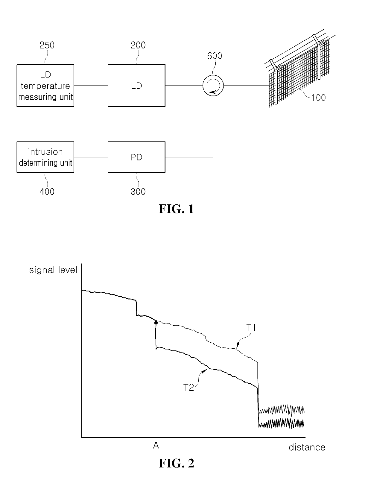
[0039]Hereinafter, embodiments of the present disclosure will be described in detail with reference to the accompanying drawings. In describing the present disclosure, if it is determined that a detailed description of known functions and components associated with the present disclosure unnecessarily obscure the gist of the present disclosure, the detailed description thereof will be omitted. The terms used henceforth are used to appropriately express the embodiments of the present disclosure and may be altered according to a person of a related field or conventional practice. Accordingly, the terms should be defined on the basis of the entire content of this specification.

[0040]Hereinafter, a method of detecting an intrusion by reflecting a change in temperature of a laser diode will be described with reference to FIGS. 1 to 6.

[0041]First, an intrusion detecting system to which an intrusion detecting method according to an embodiment of the present disclosure is applied will be de...


PUM


Abstract

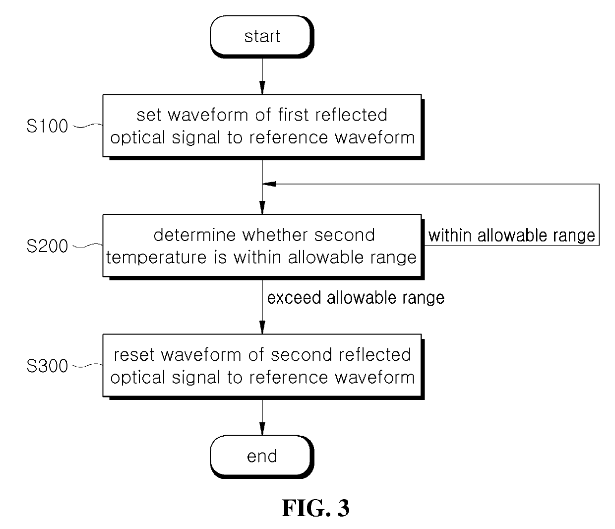
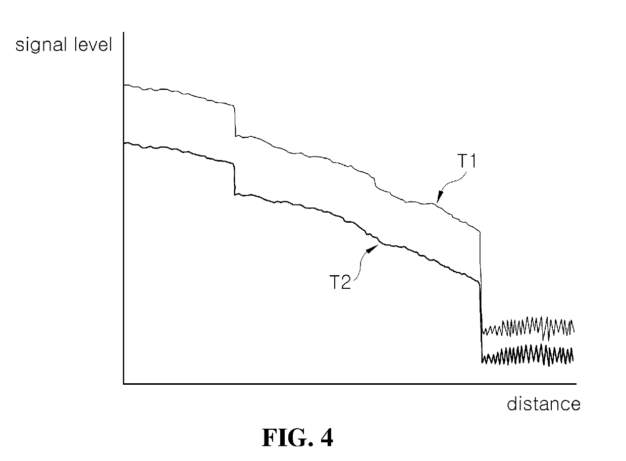
An intrusion detecting method using an intrusion detecting system which includes an optical fiber line installed in an area in which intrusion is to be detected, a laser diode inputting an optical signal to the optical fiber line, a photodiode detecting a reflected optical signal when the optical signal is reflected from the optical fiber line, an intrusion determining unit comparing a waveform of the reflected optical signal detected by the photodiode with a set reference waveform to determine whether an intrusion has occurred, and a laser diode temperature measuring unit measuring a temperature of the laser diode, includes designating, by the intrusion determining unit, a temperature of the laser diode at a first point in time as a first temperature and setting, to a reference waveform, a waveform of a first reflected optical signal caused by an input optical signal input by the laser diode at the first point in time, designating, by the intrusion determining unit, a temperature of the laser diode at a second point in time after the first point in time as a second temperature and determining whether the second temperature is within an allowable range with respect to the first temperature, and when it is determined that the second temperature exceeds the allowable range, resetting, by the intrusion determining unit, to the reference waveform, a waveform of a second reflected optical signal caused by an input optical signal input by the laser diode at the second point in time.

Description

CROSS-REFERENCE TO RELATED APPLICATION(S)[0001]The present application claims priority to Korean patent application No. 10-2017-0157866 filed on Nov. 24, 2017, the entire content of which is hereby incorporated by reference.BACKGROUND OF THE INVENTIONField of the Invention[0002]The present disclosure relates to a method for detecting an intrusion, and more particularly, to an intrusion detecting method using an intrusion detecting system using an optical fiber line.Description of the Related Art[0003]Security fences are installed in facilities and areas requiring security in many cases. Surveillance personnel may also be deployed to monitor an intrusion into the security fences. However, surveillance by surveillance personnel incurs high maintenance cost and has low monitoring accuracy.[0004]In recent years, monitoring methods using CCTVs have widely been used. With this method, input workforce may be reduced but captured images must be directly monitored by a person. In addition, i...

Claims


Application Information

Patent Timeline
Patent Type & Authority Applications(United States)
IPC IPC(8): G08B13/24G08B13/12G08B13/186
CPCG08B13/2491G08B13/124G08B13/186G08B29/185G01D21/02G01J5/10G01J2001/446G01V8/10G08B13/181G08B21/182
Inventor BYUN, JAE HEE
Owner SEUNGJAE
Learn More