
Locomotive sensor system for monitoring engine and lubricant health

a sensor system and locomotive technology, applied in the direction of locomotives, instruments, mechanical equipment, etc., can solve the problems of reducing the effectiveness and performance of lubricant, affecting the operation of machinery, and affecting the health of lubricant, so as to achieve efficient and safe operation of machinery.

Pending Publication Date: 2019-05-23
GE GLOBAL SOURCING LLC
View PDF0 Cites 50 Cited by
  • Summary
  • Abstract
  • Description
  • Claims
  • Application Information

AI Technical Summary

Benefits of technology

The patent describes a system and method for monitoring the health of oil in an engine or equipment. The system includes a sensor that generates stimuli and a processor that analyzes signals from the sensor to determine the pH level of the oil. This information indicates the condition of the oil and can help identify potential health issues in the engine or oil. The technical effect of the patent is to provide a tool for monitoring oil health in real-time, which can help prevent damage to the engine or equipment and improve operational efficiency.

Problems solved by technology

The quality of a lubricant may deteriorate over time due to the introduction of contaminants and / or aging of the lubricant.
Such additives also break down in service over time.
The acidic components can reduce the effectiveness and performance of the lubricant.
This process is inefficient to provide timely information on the condition of the oil and hence on the health of the engine and also to provide real time information on oil consumption rate.
Use of this fast response, real-time oil quality / health monitoring eliminates possible mistakes or mishaps caused by mishandled or mislabeled oil samples, oil sample bottles lost in transit, analysis reports that are incorrectly numbered or mislabeled, the normal 15 to 30 days required to complete the oil analysis (being too long), and resulting in engine failure and road failure of the vehicle if the quality of the oil (used) is very close to an end-of-life limit, etc.

Method used


Image

  • Locomotive sensor system for monitoring engine and lubricant health
  • Locomotive sensor system for monitoring engine and lubricant health
  • Locomotive sensor system for monitoring engine and lubricant health

Examples


Embodiment Construction

[0132]Unless defined otherwise, technical and scientific terms used herein have the same meaning as is commonly understood by one of ordinary skill in the art to which this specification belongs. The terms “first”, “second”, and the like, as used herein do not denote any order, quantity, or importance, but rather are used to distinguish one element from another. Also, the terms “a” and “an” do not denote a limitation of quantity, but rather denote the presence of at least one of the referenced items. The term “or” is meant to be inclusive and mean one, some, or all the listed items. The use of “including,”“comprising” or “having” and variations thereof herein are meant to encompass the items listed thereafter and equivalents thereof as well as additional items. The terms “connected” and “coupled” are not restricted to physical or mechanical connections or couplings, and can include electrical connections or couplings, whether direct or indirect. Furthermore, the terms “circuit”, “ci...


PUM


Abstract

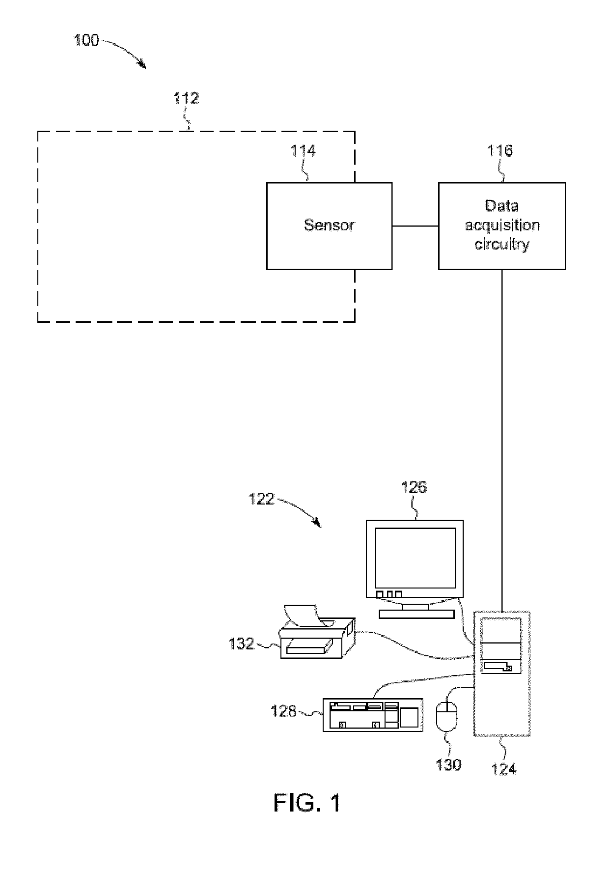
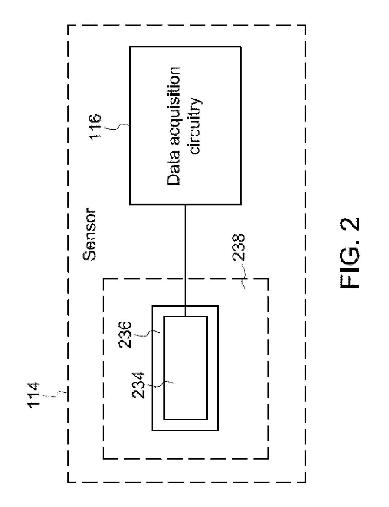
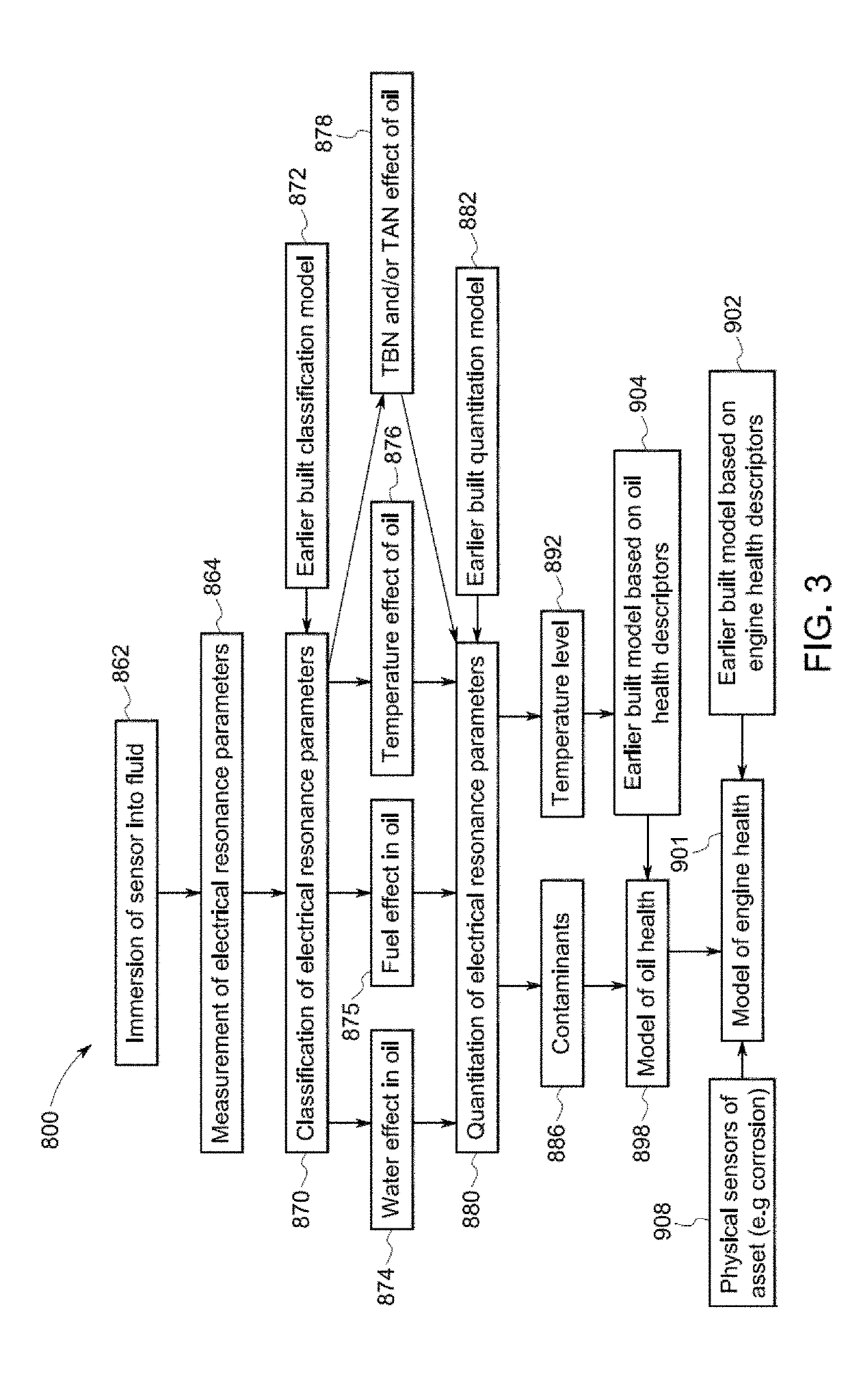
A locomotive sensor system includes a sensor configured to be in contact with lubricant within an engine of a locomotive. The sensor includes a sensing region circuit that is configured to generate stimuli at different times during an operational life of the engine. The system also includes one or more processors configured to receive signals from the sensor. The signals are representative of responses of the lubricant to the stimuli. The one or more processors are configured to analyze the responses and determine a characteristic of the lubricant that represents one or more of a total base number (TBN) or a total acid number (TAN) of the lubricant. The are configured to determine an unhealthy state of one or more of the engine or the lubricant based on the characteristic of the lubricant that is determined.

Description

CROSS-REFERENCE TO RELATED APPLICATIONS[0001]This application is a continuation-in-part of U.S. patent application Ser. No. 15 / 884,889, filed 31 Jan. 2018, U.S. patent application Ser. No. 15 / 187,934, filed 21 Jun. 2016, U.S. patent application Ser. No. 15 / 271,692, filed 21 Sep. 2016, U.S. patent application Ser. No. 15 / 060,193, filed 3 Mar. 2016, U.S. patent application Ser. No. 15 / 270,442, filed 20 Sep. 2016, U.S. patent application Ser. No. 15 / 285,415, filed 4 Oct. 2016, U.S. patent application Ser. No. 15 / 418,820, filed 30 Jan. 2017, U.S. patent application Ser. No. 15 / 365,127, filed 30 Nov. 2016, and U.S. patent application Ser. No. 16 / 146,322, filed 28 Sep. 2018.[0002]U.S. patent application Ser. No. 15 / 884,889 claims priority to U.S. Provisional Application No. 62 / 459,806, filed on 16 Feb. 2017, and is a continuation-in-part of U.S. patent application Ser. No. 14 / 585,690, which was filed on 30 Dec. 2014.[0003]U.S. patent application Ser. No. 14 / 585,690 claims priority to U.S....

Claims


Application Information

Patent Timeline
Patent Type & Authority Applications(United States)
IPC IPC(8): G07C5/08F16N29/04B61C17/08
CPCG07C5/0816G07C5/0808F16N29/04B61C17/08F16N2200/00F16N2200/08Y02T30/00
Inventor POTYRAILO, RADISLAV ALEXANDROVICHTOKAREV, IGORKUZHIYIL, NAJEEB M.OTTIKKUTTI, PRADHEEPRAM
Owner GE GLOBAL SOURCING LLC
Learn More