
Boiler cleaning process, corresponding device and boiler

a technology for cleaning process and boiler, applied in combustion process, fuel additives, combustion treatment, etc., can solve the problems of reducing the overall efficiency and performance of the boiler, reducing the availability of facilities and the lifetime of the affected exchanger, and reducing the efficiency and performan

Active Publication Date: 2019-05-23
CNIM ENVIRONNEMENT& ENERGIE SERVICES
View PDF0 Cites 0 Cited by
  • Summary
  • Abstract
  • Description
  • Claims
  • Application Information

AI Technical Summary

Benefits of technology

The present invention provides a process for reducing the number and duration of boiler cleaning stoppages and also preventing corrosion phenomena caused by molten salts. The process involves the use of magnesium and / or calcium oxide particles that react with the molten salts, resulting in the formation of higher melting temperatures. By implementing this process, the inventors have observed a significant improvement in the exchange coefficient and reduced pressure loss, which explain the reduced speed of the exhaust fan and the decreased temperature of the fumes leaving the boiler in the first case, as compared to the second case where the process is not used. The device described in this patent facilitates the carrying out of the process.

Problems solved by technology

Boilers, and in particular those installed downstream from combustion devices that combust fuels in particular containing a mineral fraction, become dirty over time, resulting in decreased efficiency and performance.
In addition to these deposits, which alter the overall exchange coefficient and therefore reduce the overall efficiency and performance of the boiler, the molten salts not crystallized create an electrolyte responsible for corrosion phenomena that may go as far as piercing the tubes of the exchanger and stopping the boiler, thereby decreasing the availability of the facility and the lifetime of the affected exchangers.
These cleaning operations are costly and generate facility downtime, the cost of which is extremely high, in particular when they occur during the maximum energy sales season.
There is additionally a risk of mechanical stressing and leakage of the exchangers upon each restart, requiring a new immobilization of the facilities for repairs.
Furthermore, the aforementioned current techniques suffer from certain drawbacks: the mechanical cleaning devices (shot peening, striking), due to the mechanical stresses induced, reduce, sometimes considerably, the lifetime of the surfaces of the exchangers (erosion by the steel beads, stress phenomena related to the shockwaves from the striking, etc.); the use of explosion techniques is effective, but very costly, and entails a non-negligible risk for operators during handling of the explosive gases; using steam causes mechanical wear problems and decreases the net steam production performance; furthermore, increasing the steam in the fumes affects the acid dew point, which may lead to corrosion phenomena in the cold parts of the boiler; the use of products in powdered form also has drawbacks, since the product, the grains of which have a diameter generally greater than 10 μm (close to the mean size of the particles that make up the ash), have a physical, and not chemical, action inasmuch as, the contact surface being small, the chemical reactions between solids are not significant, or are even practically nonexistent.
More generally, DE4446913 does not teach how to clean a boiler, since the implementation of its process makes it possible, in addition to limiting NOx emissions, to simply limit the share of combustion residues in the material resulting from the combustion due to the fact that the oxidation of the partially burned or unburned compounds is catalyzed.
More generally, the process of DE3318374 does not ensure cleaning of the boilers, except perhaps in the scenario where part of the aforementioned “large” oxide particles is not consumed by reacting with the sulfur oxides and then acts physically, i.e., mechanically, on the surface of the exchangers, in exactly in the same way as the cleaning techniques using powders or other powdered solids, as previously mentioned.

Method used


Image

  • Boiler cleaning process, corresponding device and boiler

Examples


Embodiment Construction

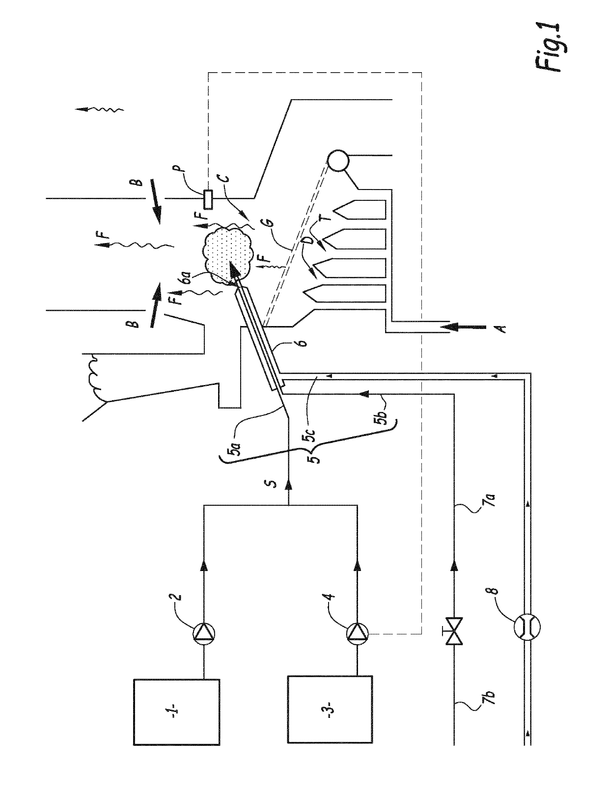
[0056]FIG. 1 shows a boiler equipped with a cleaning device that will be outlined later. The boiler has a combustion chamber C where fumes F resulting from the combustion of fuels are emitted. In the example of FIG. 1, the combustion, in particular of waste or biomass, is done on a grate G installed in the combustion chamber C, primary air A for the primary combustion of the fuels being injected below the grate, if applicable in a staged manner via distribution boxes including a second primary air injection box, referenced D in FIG. 1, and a third primary air injection box, referenced T in FIG. 1. Secondary air B can be injected in the combustion chamber C, in a zone of the latter which, in the example of FIG. 1, is situated above the grate G, the secondary air B being supplied through walls of the combustion chamber: the fumes F, which are produced in a so-called lower part of the furnace of the combustion chamber C, where the primary combustion develops and which, in the example o...


PUM


Abstract

Disclosed is a process for cleaning a boiler, wherein, while fumes are emitted in a combustion chamber of the boiler and circulate up to exchangers of the boiler, an aqueous solution of dissolved magnesium chloride and / or sulfate and / or dissolved calcium chloride is injected into the combustion chamber in the form of droplets which, by vaporization of the water of the aqueous solution, then thermal decomposition, are transformed in the combustion chamber into magnesium and / or calcium oxide particles reacting in the combustion chamber by mixing with molten salts and / or molten oxides, present in the fumes, to crystallize these molten salts and / or to vitrify these molten oxides before these molten salts and / or these molten oxides come into contact with the exchangers. Also disclosed is a device for implementing this process and a boiler equipped with this device.

Description

BACKGROUND OF THE INVENTIONField of the Invention[0001]The present invention relates to a boiler cleaning process, and a device for carrying out this process. The present invention also relates to boilers equipped with such a device.Description of the Related Art[0002]Boilers, and in particular those installed downstream from combustion devices that combust fuels in particular containing a mineral fraction, become dirty over time, resulting in decreased efficiency and performance. The dirtying of the boilers in particular corresponds to the deposition, on the surface of their exchangers, of layers of oxide mixtures and salt mixtures of various natures. In general, the fumes in the boilers comprise carbon dioxide (CO2), oxygen (O2), nitrogen (N2), steam and solids suspended in the gases, the solids being made up of mixtures of molten oxides (calcium, sodium and potassium aluminosilicates) and molten salt mixtures (alkali, alkali earth and heavy metal chlorides and sulfates, for examp...

Claims


Application Information

Patent Timeline
Patent Type & Authority Applications(United States)
IPC IPC(8): F23J15/00F23J3/02
CPCF23J15/003F23J3/023F23J7/00C10L10/04
Inventor TABARIES, FRANKLABOREL, YANNFEILENREITER, THOMAS
Owner CNIM ENVIRONNEMENT& ENERGIE SERVICES
Learn More