Oilway Arrangement for a Transmission Housing

a technology of oilway arrangement and transmission housing, which is applied in the direction of belt/chain/gearing, vehicle components, gear lubrication/cooling, etc., can solve the problem of reducing the shift quality of the transmission

Active Publication Date: 2019-05-23
ZF FRIEDRICHSHAFEN AG
View PDF0 Cites 2 Cited by
  • Summary
  • Abstract
  • Description
  • Claims
  • Application Information

AI Technical Summary

Benefits of technology

[0004]Example aspects of the present invention provide an oil guidance arrangement for a transmission housing and a transmission housing including the oil guidance arrangement of the types described at the outset, in which turbulence in the oil guidance can be avoided to the greatest extent possible.
[0005]Therefore, an oil guidance arrangement for a transmission housing of a vehicle is provided, which includes at least one approximately annular or annular disk-shaped oil slinger for collecting radially outward flowing oil. In order to avoid turbulence and, therefore, damage and pressure drops in the oil flow, it is provided that a guide area for generating a laminar oil flow, which is at least in part closed and includes at least one inflow opening and at least one outflow opening, is provided on the circumferential area of the oil slinger.
[0006]In this way, the oil flow is kept laminar at least between the inflow opening and the outflow opening due to the utilization of the guide area according to example aspects of the invention, and so spurious foaming of the oil is prevented or reduced to a minimum.
[0008]According to a next refinement of the present invention, it is provided that a radially directed oil flow flows in through the inflow opening of the guide area and can be diverted by the guide area into a tangentially aligned oil flow which flows out of the outflow opening of the guide area as an axially aligned oil flow. Due to the fact that the oil flow flows along the turbine blade geometry in the guide area, the initially radially aligned oil flow is converted into a tangential flow and, on the outflow side, into an axial flow. As a result, the occurrence of turbulence is prevented.

Problems solved by technology

It has been shown that the foamed oil can result in cavitations and pressure drops in the oil pump, which results, on the one hand, in damage and, on the other hand, in a reduction of the shift quality of the transmission.

Method used


Image

  • Oilway Arrangement for a Transmission Housing
  • Oilway Arrangement for a Transmission Housing
  • Oilway Arrangement for a Transmission Housing

Examples


Embodiment Construction

[0021]Reference will now be made to embodiments of the invention, one or more examples of which are shown in the drawings. Each embodiment is provided by way of explanation of the invention, and not as a limitation of the invention. For example, features illustrated or described as part of one embodiment can be combined with another embodiment to yield still another embodiment. It is intended that the present invention include these and other modifications and variations to the embodiments described herein.

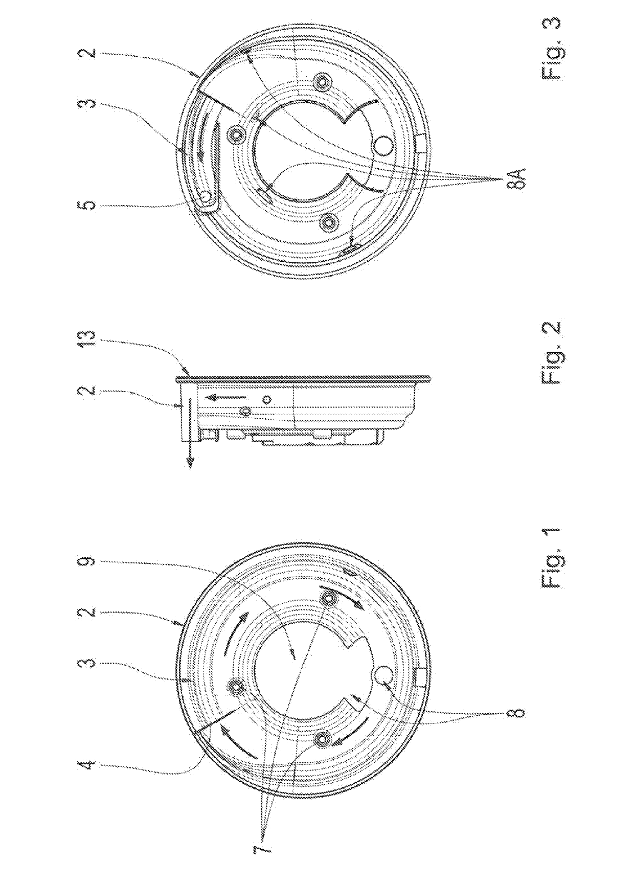
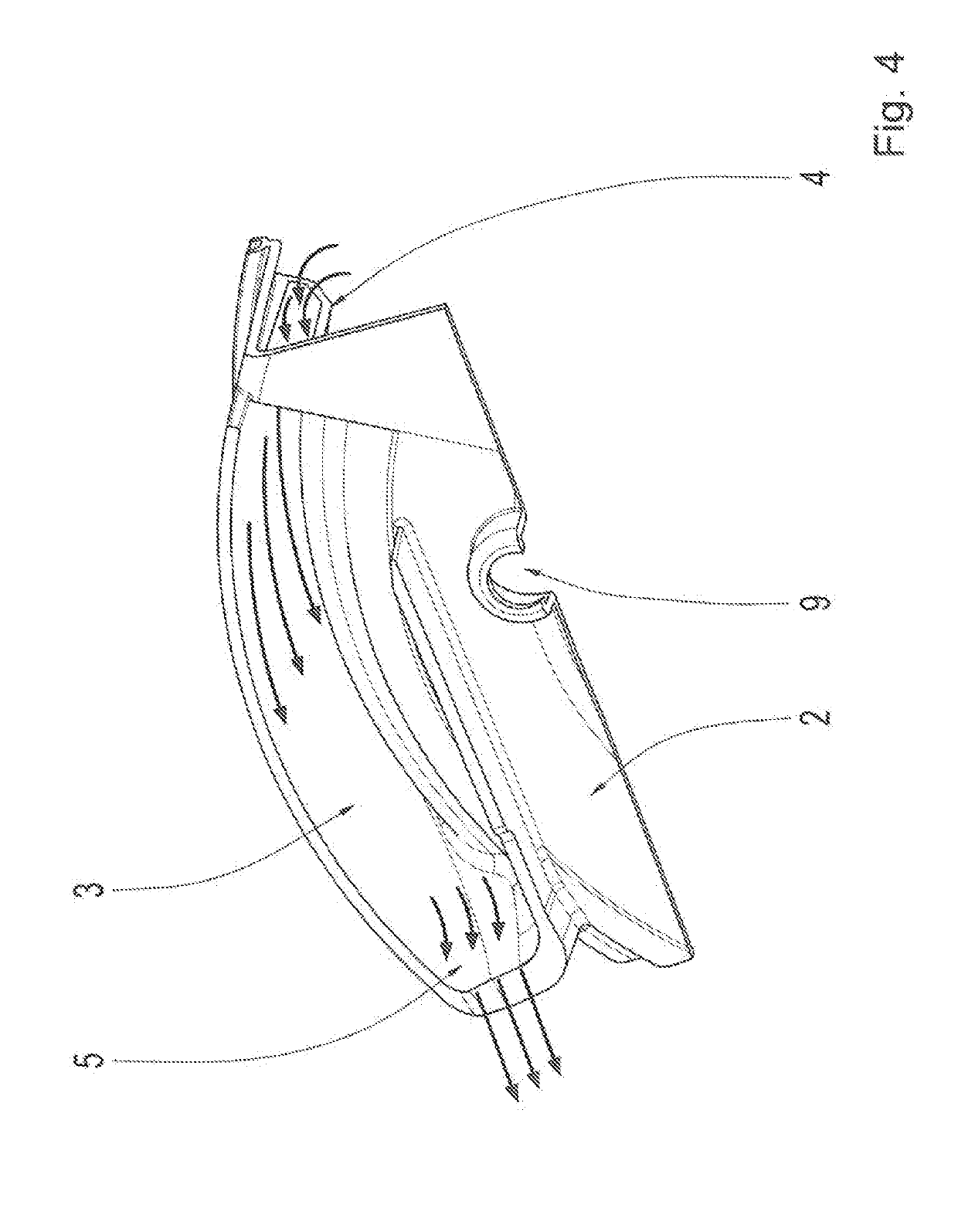
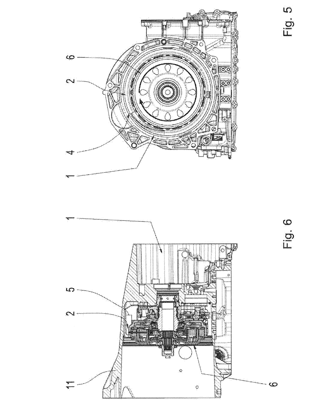
[0022]In FIGS. 1 through 4, various views of an oil guidance arrangement according to example aspects of the invention are represented by way of example, while various views of a transmission housing 1 including the installed oil guidance arrangement are shown by way of example in FIGS. 5 through 9.

[0023]The oil guidance arrangement according to the invention includes an approximately annular disk-shaped oil slinger 2 for collecting radially outward flowing oil. In order to avoid ...


PUM


Abstract

An oil guidance arrangement for a transmission housing (1) of a vehicle includes at least one annular oil slinger (2) for collecting radially outward flowing oil. A guide area (3) for generating a laminar oil flow is closed in sections and is provided on a circumferential area of the oil slinger (2). A transmission housing (1) includes the oil guidance arrangement. The oil slinger (2) of the oil guidance arrangement is attached to a transmission housing-side centering plate (10) and surrounds a clutch (6). By rotation of the clutch (6), oil is guidable radially outward to the guide area (3) of the oil slinger (2).

Description

FIELD OF THE INVENTION[0001]The present invention relates generally to an oil guidance arrangement for a transmission housing of a vehicle, including at least one annular oil slinger for collecting radially outward flowing oil. The present invention further relates generally to a transmission housing including the oil guidance arrangement.BACKGROUND[0002]Oil guidance arrangements with an oil slinger for a transmission housing of a vehicle are known. The known oil guidance arrangements usually include an oil slinger having a form of a partial circle or even having a form of a full circle in order to collect the oil in the interior space of the transmission housing and return the oil into an oil sump of the transmission housing. In the transmission housing, oil is conveyed radially outward from a radial gap between a clutch and the oil slinger in order to reduce drag losses in the clutch. Due to the high rotational speeds, the radially outward flowing oil hits the oil slinger at high ...

Claims


Application Information

Patent Timeline
Patent Type & Authority Applications(United States)
IPC IPC(8): F16H57/04
CPCF16H57/0423F16H57/0457F16N2210/12F16N2210/04F16H57/04
Inventor ZWERGER, NIKONOTHEIS, PHILIPP
Owner ZF FRIEDRICHSHAFEN AG
Why Eureka
Try Eureka