
Tire vulcanization mold and manufacturing method thereof

Active Publication Date: 2019-05-23
TOYO TIRE & RUBBER CO LTD
View PDF0 Cites 0 Cited by
  • Summary
  • Abstract
  • Description
  • Claims
  • Application Information

AI Technical Summary

Benefits of technology

The tire vulcanization mold described in this patent has the advantage that it allows for easier removal of tires from the mold. This is achieved because the rubber does not stick to the mold's sipe blade. The manufacturing method for this mold is also provided.

Problems solved by technology

In such a case, the rubber 244 may later fall into the mold and adhere to an unvulcanized tire before subjected to vulcanization molding, thereby making the tire defective.
In addition, cracking occurs in a sipe edge in some cases when rubber in a through-hole is torn off.

Method used


Image

  • Tire vulcanization mold and manufacturing method thereof
  • Tire vulcanization mold and manufacturing method thereof
  • Tire vulcanization mold and manufacturing method thereof

Examples


Embodiment Construction

[0024]A present embodiment will be described according to the drawings. It should be appreciated that the present embodiment is a mere example and any change made as needed without deviating from the gist of the present invention is included within the scope of the present invention. In the drawings, a length, a shape, or the like may be exaggerated or represented schematically for ease of description. It should be appreciated, however, that the drawings are mere an example and by no means limit an interpretation of the present invention.

1. Structures of Tire Vulcanization Mold 10 and Sipe Blade 26

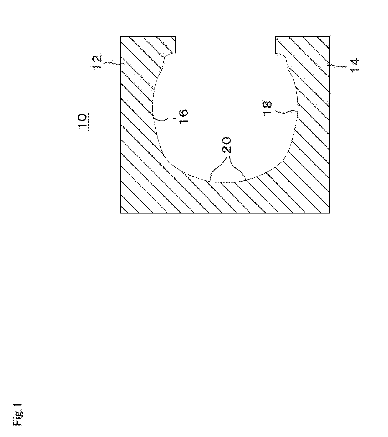
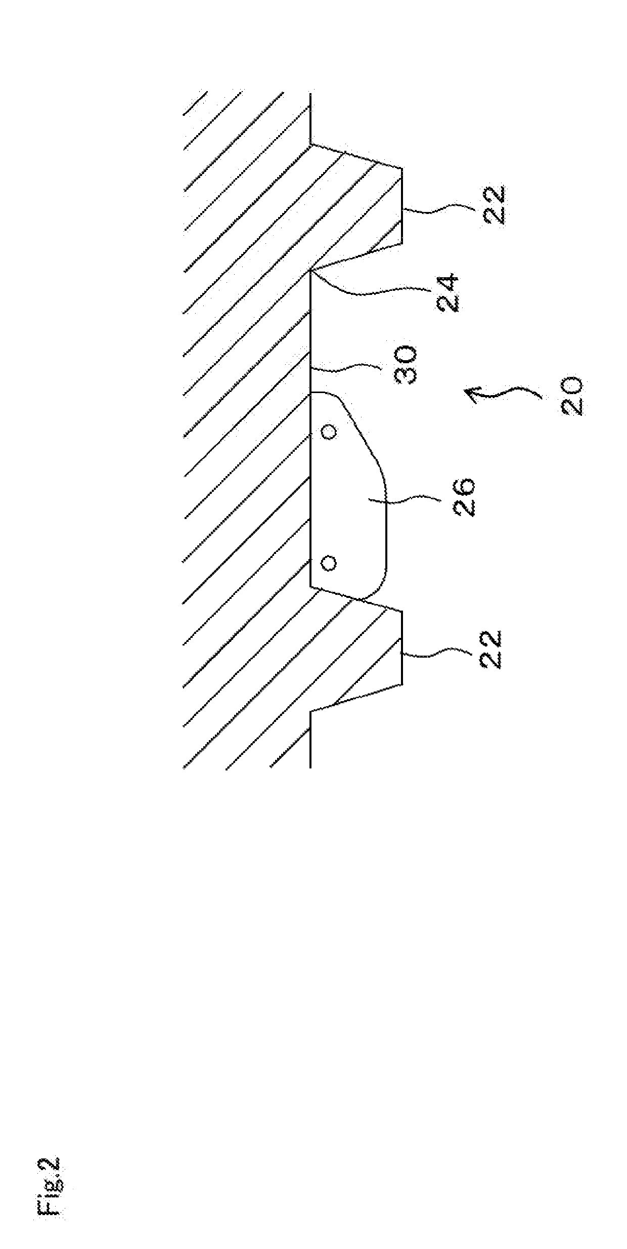
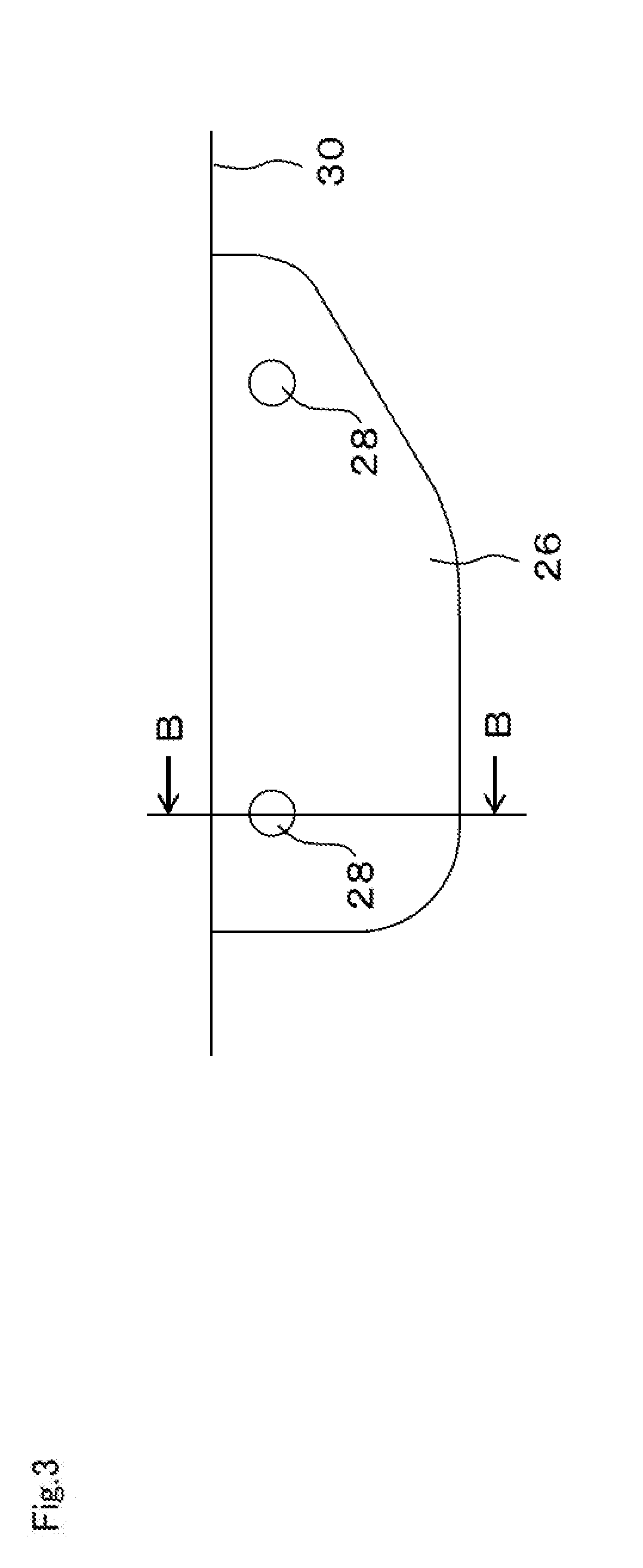
[0025]FIG. 1 shows a tire vulcanization mold 10 of one embodiment. The tire vulcanization mold 10 has an upper mold 12 and a lower mold 14. The upper mold 12 has an upper-side molding portion 16 which is a recess opening downward. The lower mold 14 has a lower-side molding portion 10 which is a recess opening upward. During vulcanization molding, an unvulcanized tire is se on the lower sid...


PUM

PropertyMeasurementUnit
Diameteraaaaaaaaaa
Lengthaaaaaaaaaa
Lengthaaaaaaaaaa

Abstract

A tire vulcanization mold 10 has a plate-like sipe blade 26 used to form a sipe in a tread portion of a pneumatic tire. The sipe blade 26 protrudes to a mold inner side from a mold inner surface 30, and is provided with a through-hole 28 drilled to penetrate through the sipe blade 26. An acute angle portion is formed between a surface 29a of the through-hole 28 on the mold inner side and a surface 27 of the sipe blade 26, and a diameter of the through-hole 28 is larger than 1 mm.

Description

REFERENCE TO RELATED APPLICATION[0001]The present application is based on Japanese Patent Application No. 2017-224761 (filing date: Nov. 22, 2017) and claims the benefit of Japanese Patent Application No. 2017-224761. The entire subject matter of Japanese Patent Application No. 2017-224761 is hereby incorporated herein by referring to Japanese Patent Application No. 2017-224761.TECHNICAL FIELD[0002]The present invention relates to a tire vulcanization mold and a manufacturing method thereof.BACKGROUND ART[0003]A plate-like sipe blade is provided inside a tire vulcanization mold to form a sipe in a tread portion of a pneumatic tire. As is shown in FIG. 14A, through-holes 228 are drilled in a sipe blade 226 to let air and rubber pass through during vulcanization molding.[0004]As is indicated by an arrow in FIG. 14B, rubber fills in the through-hole 228 during vulcanization molding, when the mold is opened to remove a tire after the rubber sets, as is shown in FIG. 14C, rubber 244 in t...

Claims


Application Information

Patent Timeline
IPC IPC(8): B29D30/06B29C33/38
CPCB29D30/0606B29C33/3842B29D2030/0613B29D2030/0617
Inventor FUJIKI, KUNIKO
Owner TOYO TIRE & RUBBER CO LTD
Learn More