
Light distribution module

a technology of light distribution module and light distribution module, which is applied in the direction of fixed installation, lighting and heating equipment, roads, etc., can solve the problems of long development period of road lighting devices, increased maintenance cost, and high cost of road lighting devices

Active Publication Date: 2019-05-16
LEOTEK CORP
View PDF12 Cites 0 Cited by
  • Summary
  • Abstract
  • Description
  • Claims
  • Application Information

AI Technical Summary

Benefits of technology

The invention is a light distribution module that includes a lens and an optical cover. The lens and optical cover produce two different light shapes, which can be rotated. This allows the module to create a variety of light patterns with just a few different designs for the optical cover.

Problems solved by technology

However, road lighting devices often require a long development period and are costly.
Furthermore, the need for each additional optical cover also means an additional maintenance cost.

Method used


Image

  • Light distribution module
  • Light distribution module
  • Light distribution module

Examples


Embodiment Construction

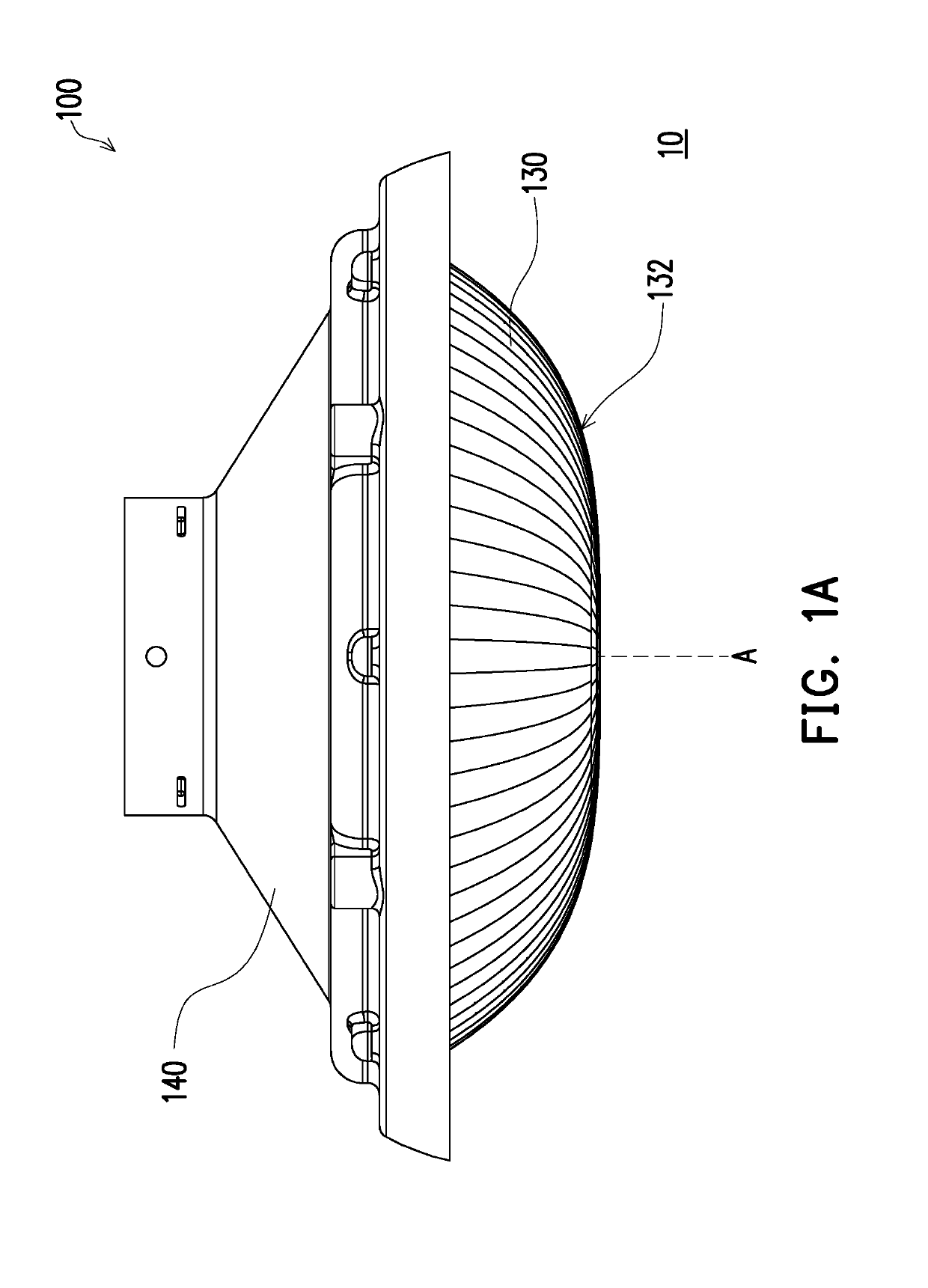
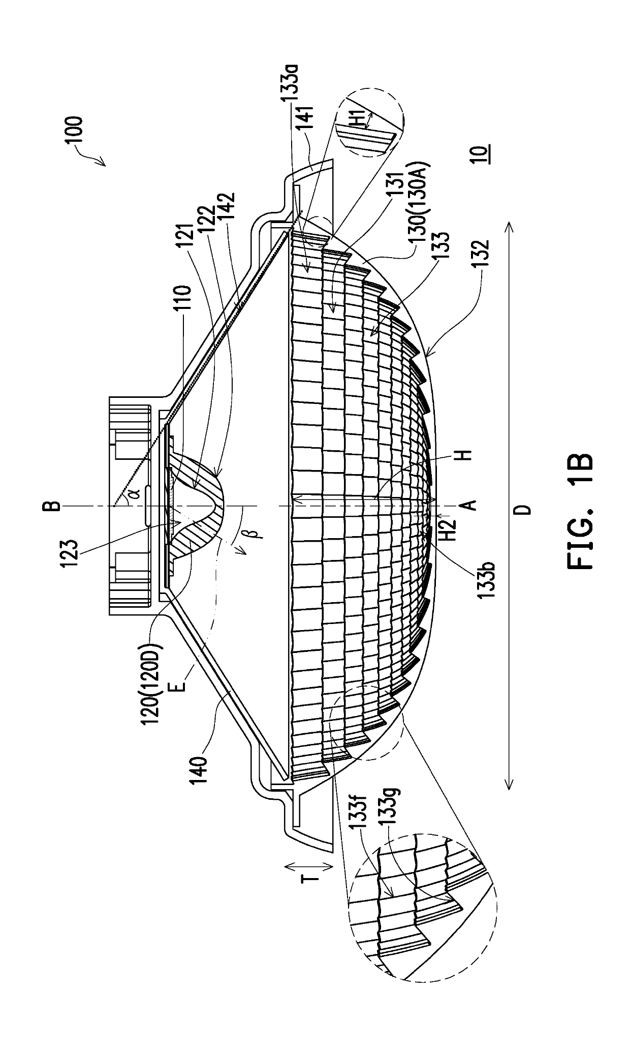
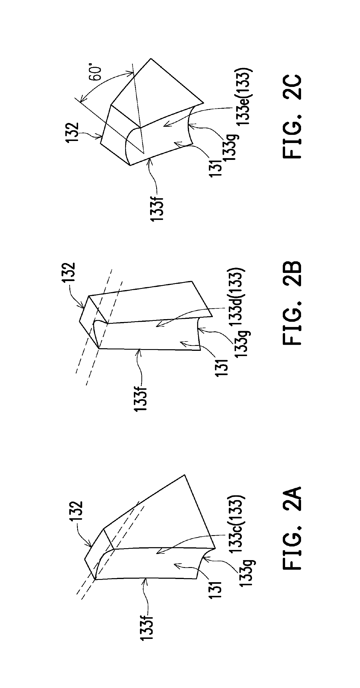
[0047]FIG. 1A shows a side view of a lighting device of the first embodiment of the invention. FIG. 1B is a cross-section of the lighting device of FIG. 1A cut along an optical axis A. FIGS. 2A to 2C are schematics of three kinds of sub-curved surfaces of an optical cover in an embodiment of the invention. FIGS. 3A to 3B are perspective views of a lens of an embodiment of the invention. FIG. 3C and FIG. 3D are respectively cross-sections of the lens of FIG. 3B along a second long axis B2 and a first long axis B1. FIGS. 4A to 4B are perspective views of a lens of another embodiment of the invention. FIG. 4C and FIG. 4D are respectively cross-sections of the lens of FIG. 4B along a longitudinal direction B3 and a lateral direction B4. FIGS. 5A to 5B are perspective views of a lens of yet another embodiment of the invention. FIG. 5C and FIG. 5D are respectively cross-sections of the lens of FIG. 5B along the longitudinal direction B3 and the lateral direction B4. FIGS. 6A to 6B are per...


PUM


Abstract

A light distribution module configured to control a light distribution of a light source is provided. The light distribution module includes a lens and an optical cover. The lens has a first light-incident surface, a first light-emitting surface opposite to the first light-incident surface, and an accommodating recess located at a side of the first light-incident surface, wherein the accommodating recess is configured to contain the light source. The optical cover covers the lens and has a second light-incident surface and a second light-emitting surface opposite to the second light-incident surface, wherein the second light-incident surface is located between the first light-emitting surface and the second light-emitting surface, and the second light-incident surface has a plurality of sub-curved surfaces. Boundaries between adjacent sub-curved surfaces are bent-shaped with respect to the adjacent sub-curved surfaces.

Description

CROSS-REFERENCE TO RELATED APPLICATION[0001]This application claims the priority benefits of U.S. provisional application Ser. No. 62 / 586,178, filed on Nov. 15, 2017, and China application serial no. 201811061681.7, filed on Sep. 12, 2018. The entirety of each of the above-mentioned patent applications is hereby incorporated by reference herein and made a part of this specification.BACKGROUND OF THE INVENTIONField of the Invention[0002]The invention relates to an optical module, and more particularly, to a light distribution module.Description of Related Art[0003]In the traditional lighting device design, the light source is disposed on an optical cover to produce the required light shape. For road lighting device, in order to meet the regulations and lighting requirements in different regions / countries, a lighting device often requires several kinds or even dozen kinds of optical covers.[0004]However, road lighting devices often require a long development period and are costly. Fur...

Claims


Application Information

Patent Timeline
Patent Type & Authority Applications(United States)
IPC IPC(8): F21V5/04F21V3/02F21V13/04F21S8/08
CPCF21V5/045F21V3/02F21V13/04F21S8/086F21W2111/02F21Y2115/10F21V5/08F21W2131/103
Inventor SHIH, WEI-WENWANG, SHIH-CHANG
Owner LEOTEK CORP
Learn More