
Image capturing device having power reset function

a technology of image capturing and function, applied in the field of electronic devices, can solve the problems of easy damage to the housing, consumption of working hours and manpower, and the inability to apply the person to a sealed electronic devi

Active Publication Date: 2019-05-09
CHICONY ELECTRONICS
View PDF0 Cites 1 Cited by
  • Summary
  • Abstract
  • Description
  • Claims
  • Application Information

AI Technical Summary

Benefits of technology

The invention relates to a camera device that can perform power reset without needing to disassemble or damage the camera. The device uses a magnetic reset switch that can be activated by a magnet outside of the camera. This allows for quicker and more efficient power reset, and can also be used on a sealed camera device.

Problems solved by technology

However, this manner cannot be applicable to a sealed electronic device (for example, an electronic device that is entirely waterproof).
In addition, each time the power source needs to be restarted, the housing needs to be dismantled, resulting in consumption of working hours and manpower, and easy damage to the housing.
However, this method is not applicable to the sealed electronic device either.
Consequently, the user is likely to incorrectly insert the needle into the another hole, resulting in damage to a part or a loss of a waterproof function.

Method used


Image

  • Image capturing device having power reset function
  • Image capturing device having power reset function
  • Image capturing device having power reset function

Examples


first embodiment

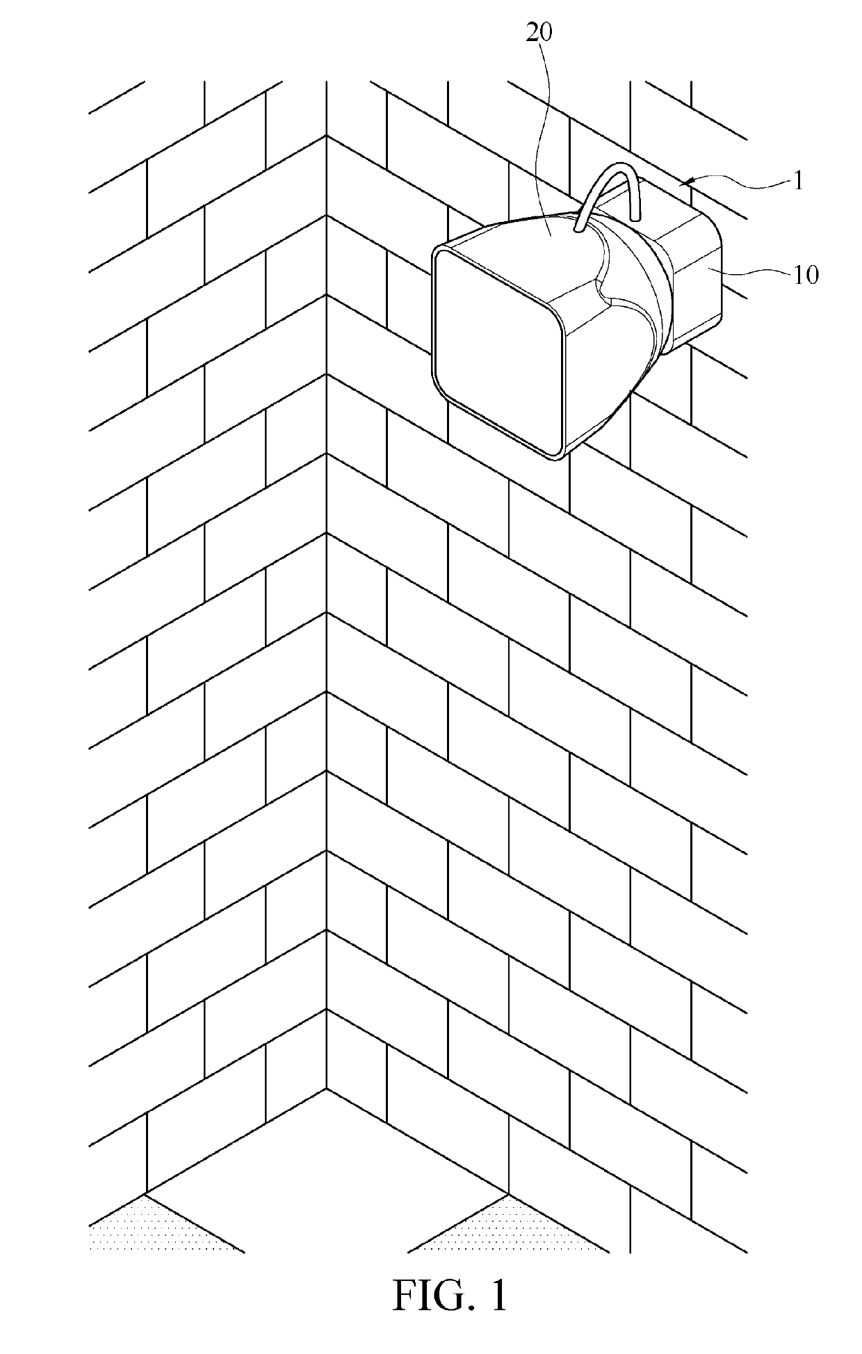
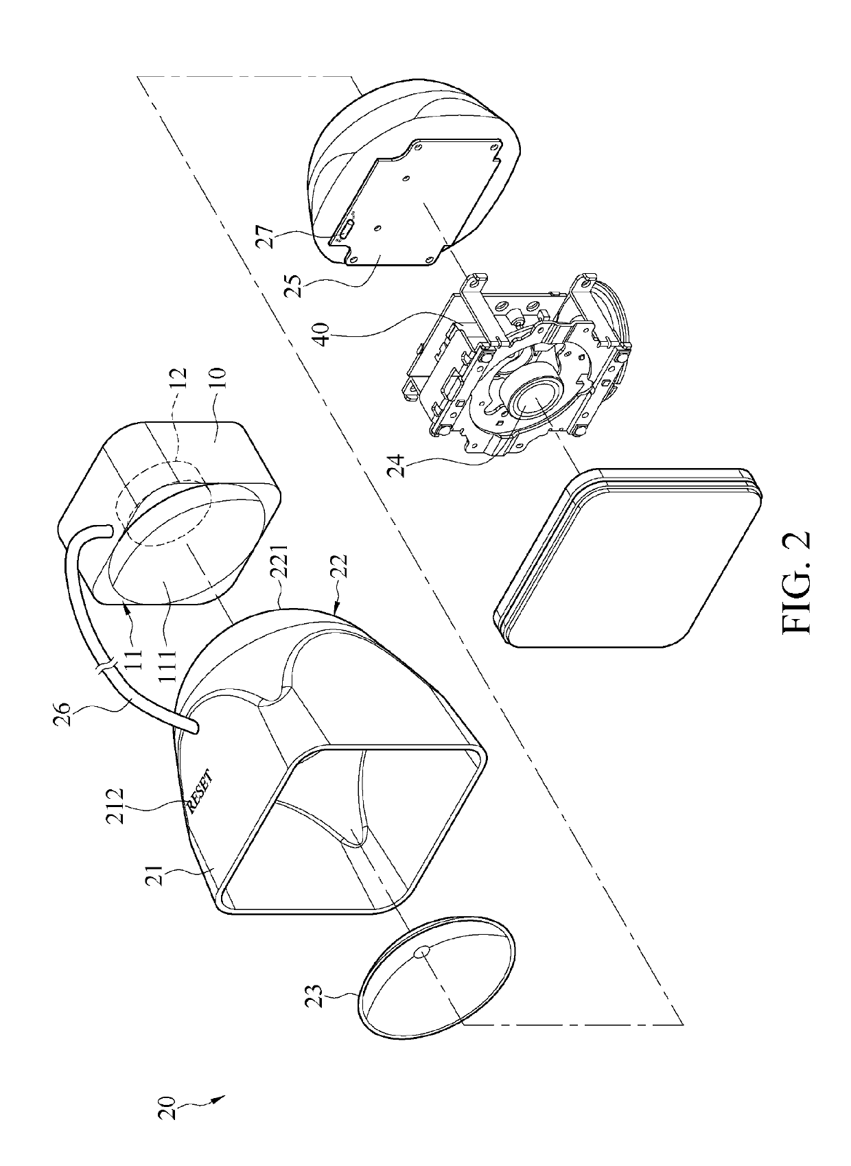
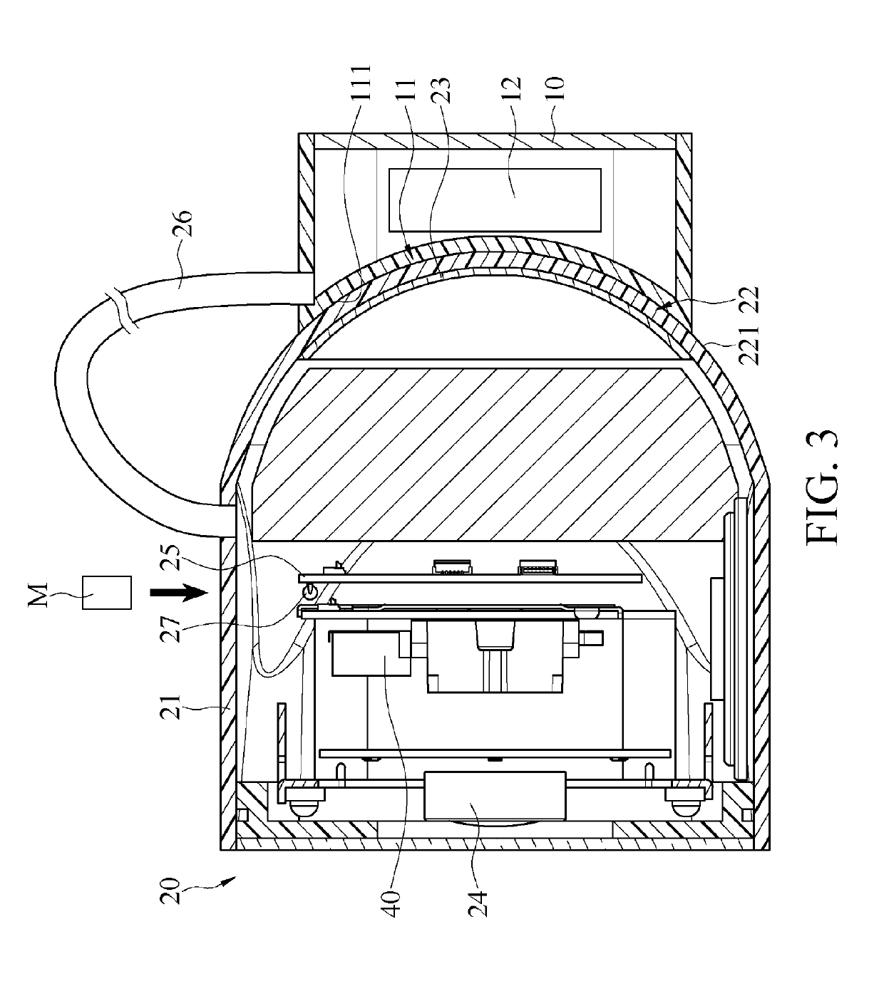
[0018]In an embodiment, the fixed base 10 of the image capturing device 1 may be assembled on a fixed object. For example, as shown in FIG. 1, in this embodiment, the fixed base 10 is fixed on a wall. Practically, the fixed base 10 may be fixed on various places (for example, a ceiling, a street lamp, a utility pole, and a dashboard) according to usage scenarios. The fixed base 10 has a first assembly portion 11 configured to assemble the camera 20. Referring to FIG. 2 and FIG. 3, FIG. 3 is a sectional view of the image capturing device according to the present invention. In this embodiment, the fixed base 10 is in the form of a housing, the first assembly portion 11 is a side face that is of the fixed base 10 and that is configured to be assembled to the camera 20, and the first assembly portion 11 is provided with a first magnetic member 12. In this embodiment as shown in the figures, the first magnetic member 12 is disposed inside the fixed base 10 and approximal to the first ass...

third embodiment

[0037]In an embodiment, the image capturing device 1 may further include other type of magnetic switch. For example, in an embodiment of FIG. 9, which is a sectional view of the image capturing device according to the present invention, the image capturing device 1 may include a magnetic alarm switch 28, and the magnetic alarm switch 28 is disposed approximal to the second assembly portion 22 of the housing 21. The magnetic alarm switch 28 may be a reed switch or a magnetic induction switch, and can sense the magnetism of the first magnetic member 12. When the magnetic alarm switch 28 is distant from the first magnetic member 12, for example, when the magnetic alarm switch 28 is outside the range of the magnetic field of the first magnetic member 12 because the camera 20 is separated from the fixed base 10, the magnetic alarm switch 28 immediately outputs an alarm signal and further has a security function. For example, the alarm signal may correspondingly drive an alerter to make a...


PUM


Abstract

An image capturing device having a power reset function includes a fixed base and a camera. The fixed base has a first assembly portion, and the first assembly portion is provided with a first magnetic member. The camera includes a housing, a circuit board, and a magnetic reset switch electrically connected to the circuit board. The housing has a second assembly portion, and the second assembly portion is provided with a second magnetic member. The second magnetic member and the first magnetic member are configured to be magnetically attracted to each other such that the second assembly portion is correspondingly assembled and disposed on the first assembly portion. The circuit board is disposed inside the housing. The magnetic reset switch is disposed inside the housing and is distant from the second assembly portion.

Description

CROSS-REFERENCE TO RELATED APPLICATION[0001]This non-provisional application claims priority under 35 U.S.C. § 119(a) to Patent Application No. 106138693 filed in Taiwan, R.O.C. on Nov. 8, 2017, the entire contents of which are hereby incorporated by reference.BACKGROUNDTechnical Field[0002]The present invention relates to an electronic device, and in particular, to an image capturing device having a power reset function.Related Art[0003]Generally, electronic devices (for example, surveillance cameras, routers, or digital assistant devices) each have a power reset function. When an electronic device cannot normally operate or is down, the electronic device may be restored to a normal operating state by restarting a power source. Currently, there are mainly several methods for restarting a power source of an electronic device, as follows.[0004]A first method is that a housing of the electronic device is dismantled, and a battery is taken out and then is reinstalled, to restart the po...

Claims


Application Information

Patent Timeline
IPC IPC(8): H04N5/232H04N5/225
CPCH04N5/23241H04N5/2252H04N1/00885H04N23/51H04N23/65G03B2217/002H04N25/709
Inventor LO, KUO-CHENGLIN, TZU-YU
Owner CHICONY ELECTRONICS
Learn More