
Audio processor and audio processing method

Active Publication Date: 2019-04-25
CLARION CO LTD
View PDF0 Cites 0 Cited by
  • Summary
  • Abstract
  • Description
  • Claims
  • Application Information

AI Technical Summary

Benefits of technology

The audio processor and audio processing method described in this patent text have a filtering process that uses a second filter coefficient to limit the signal level of the audio signal in the time domain. This filtering process prevents distortion and clipping, resulting in a smoother and more accurate sound. The audio signal is transformed into the frequency domain, and the second filter coefficient is calculated based on the gains set by the user for each band. The second filter coefficient is used to limit the gains in certain bands, preventing them from exceeding the absolute value of the second gain. This filtering process maintains the quality of the entire audio signal and increases the audio processing effect.

Problems solved by technology

For this reason, computing using an IIR filter tends to accumulate computational errors.
Accordingly, audio processing using an IIR filter disadvantageously shows low computational accuracy.
However, in audio processing using an FIR filter, it is not easy to change only the gain in a particular frequency band.
For this reason, computing using an FIR filter disadvantageously shows low frequency characteristics adjustability.

Method used


Image

  • Audio processor and audio processing method
  • Audio processor and audio processing method
  • Audio processor and audio processing method

Examples


Embodiment Construction

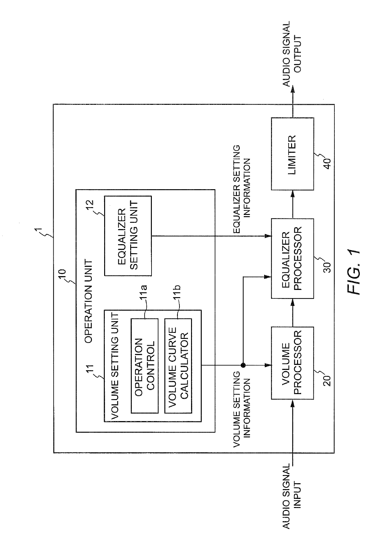
[0052]Now, an audio processor according to one embodiment of the present invention will be described in detail using an audio processor having a schematic configuration shown in FIG. 1. As shown in FIG. 1, an audio processor 1 includes an operation unit 10, a volume processor 20, an equalizer processor 30, and a limiter 40. An audio signal inputted to the audio processor 1 is processed by the volume processor 20 and equalizer processor 30 and then the level of the audio signal is limited by the limiter 40. The audio signal outputted from the limiter 40 is amplified by an amplifier (not shown) and then outputted from a speaker (not shown).

[0053][Operation Unit]

[0054]The operation unit 10 includes a volume setting unit 11 that the user operates to adjust (set) the volume and an equalizer setting unit (band gain setting unit) 12 that the user operates to adjust the gains for respective bands.

[0055][Volume Setting Unit]

[0056]The volume setting unit 11 includes a rotatable operation cont...


PUM


Abstract

An audio processor (1) includes a first filter coefficient calculator (31) that calculates a first filter coefficient so as to correspond to first gains for respective bands set by a user, a second filter coefficient calculator (32) that if values of third gains for respective bands of the first filter coefficient are greater than an absolute value of a second gain set by the user, calculates a second filter coefficient by limiting the values of the third gains for the respective bands to the amplitude value of the second gain, and a filtering unit (35) that filters an audio signal that has been transformed into a frequency-domain signal, using the second filter coefficient.

Description

TECHNICAL FIELD[0001]The present invention relates to an audio processor and audio processing method. More specifically, the present invention relates to an audio processor and audio processing method that when an audio signal exceeds an amplitude (signal level) range that can be processed (represented) by the audio processor, that is, when the audio signal exceeds a full-scale value and overflows, are able to increase the gains (signal levels) for respective bands while suppressing clipping.BACKGROUND ART[0002]Infinite impulse response (IIR) filters and finite impulse response (FIR) filters have been widely known as filters for use in audio processors.[0003]An IIR filter is characterized in that it easily adjusts the gain (signal level) in any frequency band. However, an IIR filter requires a feedback loop process in computing. For this reason, computing using an IIR filter tends to accumulate computational errors. Accordingly, audio processing using an IIR filter disadvantageously...

Claims


Application Information

Patent Timeline
IPC IPC(8): H03G9/02H03H17/02H04R3/04
CPCH03G9/02H03H17/0213H04R3/04H03G5/165H03G5/025H03G9/025H03H17/06H03H2017/0297H03H17/0294H03H2218/025H03H17/02H03G9/00H03G5/02
Inventor WATANABE, TETSUOHASHIMOTO, TAKESHI
Owner CLARION CO LTD
Learn More