Estimation of the Location of a Wireless Terminal, Based on Characterizing a Pressure Wave

Active Publication Date: 2019-04-25
POLARIS WIRELESS
View PDF0 Cites 4 Cited by
  • Summary
  • Abstract
  • Description
  • Claims
  • Application Information

AI Technical Summary

Benefits of technology

The present invention provides a system and method for estimating the location of a wireless terminal by analyzing the barometric pressure in its vicinity. The system can determine if the signals are impaired or not, and can compensate for the impairment by estimating the location based on the barometric pressure measurements. The system can also infer the probability that the wireless terminal is indoors or outdoors based on the presence of transients in the pressure wave. The accuracy of the estimate is important for various applications such as military, police, and emergency services, where the location of the wireless terminal is critical.

Problems solved by technology

In contrast, when the system does not know that the signals have been impaired or does not compensate for the impairment, the accuracy of the estimate can be very bad.
The military, police, and emergency services often rely on the estimates to be good, and a bad estimate can have serious consequences.
Signals can be impaired by natural objects such as mountains and by artificial objects such as buildings.
The impairment caused when a wireless terminal is indoors is particularly subtle, and it is particularly difficult to know that the wireless terminal is indoors, in at least some techniques in the prior art.
Although it is trivial for a human to know whether he or she is indoors or outdoors, and it might seem that it should be simple for a machine to know whether it is indoors or not, it has been a difficult problem in the prior art.

Method used


Image

  • Estimation of the Location of a Wireless Terminal, Based on Characterizing a Pressure Wave
  • Estimation of the Location of a Wireless Terminal, Based on Characterizing a Pressure Wave
  • Estimation of the Location of a Wireless Terminal, Based on Characterizing a Pressure Wave

Examples


Embodiment Construction

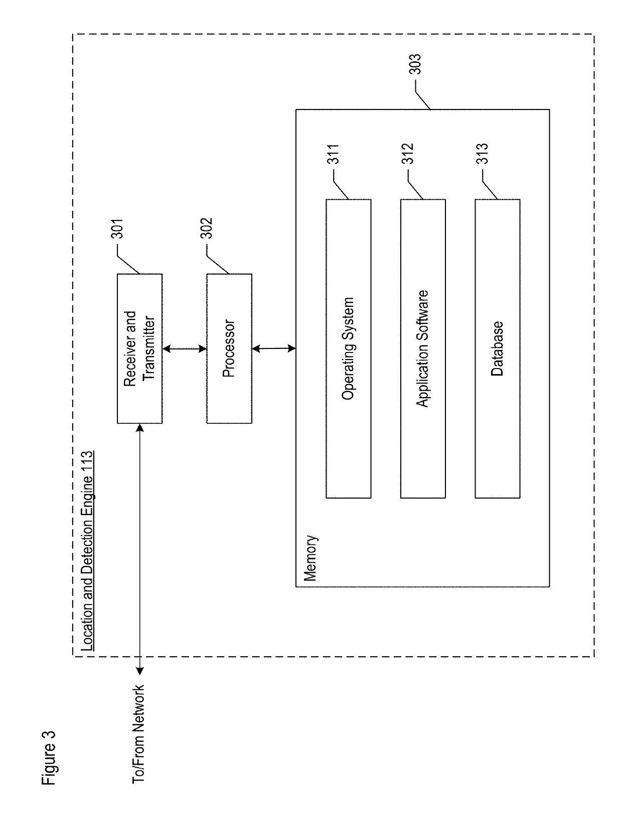
[0067]FIG. 1 depicts a diagram of the salient components of wireless telecommunications system 100 in accordance with the illustrative embodiment of the present invention. Wireless telecommunications system 100 comprises: wireless terminals 101 and 102, cellular base stations 103-1, 103-2, and 103-3, Wi-Fi base stations 104-1 and 104-2, wireless infrastructure 111, location-based application server 112, location and detection engine 113, and GPS constellation 121, interrelated as shown.

[0068]Wireless infrastructure 111, location-based application server 112, location and detection engine 113 (hereinafter “location engine 113”), and Wi-Fi base stations 104-1 and 104-2 are all connected to one or more interconnected computer networks (e.g., the Internet, a local-area network, a wide-area network, etc.) and, as such, can exchange data in well-known fashion.

[0069]Although the illustrative embodiment depicts wireless telecommunications system 100 as comprising two wireless terminals, it ...


PUM


Abstract

A technique for estimating the location of a wireless terminal at an unknown location in a geographic region. The technique is based on a two-part recognition, the first part being that a transient in atmospheric pressure attributed to a particular source, such as an entry door of a building opening and closing, is detectable in some environments while not being present in others. The second part of the recognition is that a correlation exists between i) the presence of a transient in the characterization of a pressure wave in the vicinity of a wireless terminal and ii) whether the wireless terminal is indoors or not. Transients in pressure waves are often present indoors but not outdoors. By accounting for the transients being detected or not being detected in the vicinity of the wireless terminal, the disclosed technique is able to estimate whether the wireless terminal is indoors.

Description

CROSS REFERENCE TO RELATED APPLICATIONS[0001]This application is related to “Detection Of The Occurrence Of An Event, Based On Barometric Pressure Measurements,” application Ser. No. 15 / ______, Attorney Docket 465-421u51, which is incorporated by reference herein in its entirety.[0002]This application is related to U.S. Pat. Nos. 6,518,918, 6,944,465, 7,460,505, 7,383,051, 7,257,414, 7,753,278, 7,433,695, 7,848,762, and 8,306,676, 8,630,665, and 9,332,389, each of which is incorporated by reference herein.[0003]This application is related to U.S. Patent Application Publications 2008 / 0077356, 2008 / 0077472, and 2008 / 0077516, each of which is incorporated by reference herein.FIELD OF THE INVENTION[0004]The present invention relates to telecommunications in general, and, more particularly, to a technique for estimating the location of a wireless terminal based on characterizing a pressure wave of the air in the vicinity of the wireless terminal.BACKGROUND OF THE INVENTION[0005]The salie...

Claims


Application Information

Patent Timeline
IPC IPC(8): G01D5/42G01L19/08H04W4/02
CPCG01D5/42G01L19/086H04W4/02H04W4/33G01S5/0278G01S5/012G01S5/018
Inventor BLAHA, JR., JEROME ARTHUR
Owner POLARIS WIRELESS
Why Eureka
Try Eureka