Eureka AIR delivers breakthrough ideas for toughest innovation challenges, trusted by R&D personnel around the world.

Cantilevered Screwless Hanger

Active Publication Date: 2019-04-18
HAWK CHRISTOPHER
View PDF9 Cites 0 Cited by
  • Summary
  • Abstract
  • Description
  • Claims
  • Application Information

AI Technical Summary

Benefits of technology

The present invention provides a screwless hanger that utilizes leverage and the weight of the object to be hung to support it from a vertical structure without the need for additional fasteners. This hanger is designed to be easily attached to a square post without damaging the structure. The technical effects of this invention are that it provides a convenient and safe way to support heavy objects and avoids the need for additional hardware that could damage the environment.

Problems solved by technology

The use of such fasteners requires tools that the individual may not have available at their disposal, such as a drill.
The use of fasteners to hang a support hook can also cause damage to the structure to which the support hook is secured.
Further, it is difficult and time-consuming to unfasten the fasteners if an individual wishes to remove or reposition the support hook.
For example, rental properties sometimes disallow installation of fixtures that cause damage to the supporting structure, so renters are often unable to utilize such permanently-fastened support devices.
However, the devices in the known art have several drawbacks.
These devices are typically designed to attach to round poles, and such devices would damage the corners of a square post if secured thereto.
Additionally, these devices fail to provide cantilevered support hangers that can be easily rotated about a square vertical support structure and then locked into place for installation in a desired orientation, such that further rotation is prevented when the hanger is installed.
Further, the known art cantilevered support devices fail to provide a support device specifically configured to be securable to a square post that includes inaccessible upper and lower ends, such as a baluster of a railing or fence, for example.

Method used


Image

  • Cantilevered Screwless Hanger
  • Cantilevered Screwless Hanger
  • Cantilevered Screwless Hanger

Examples


Embodiment Construction

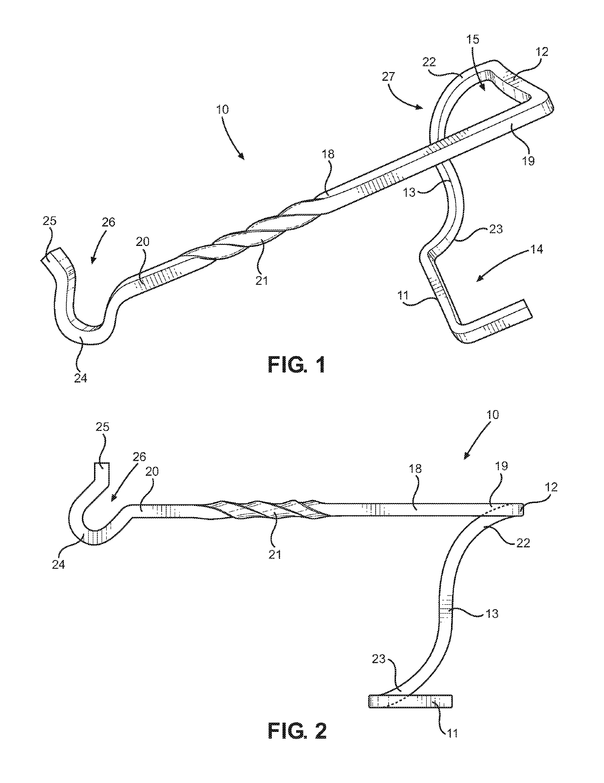
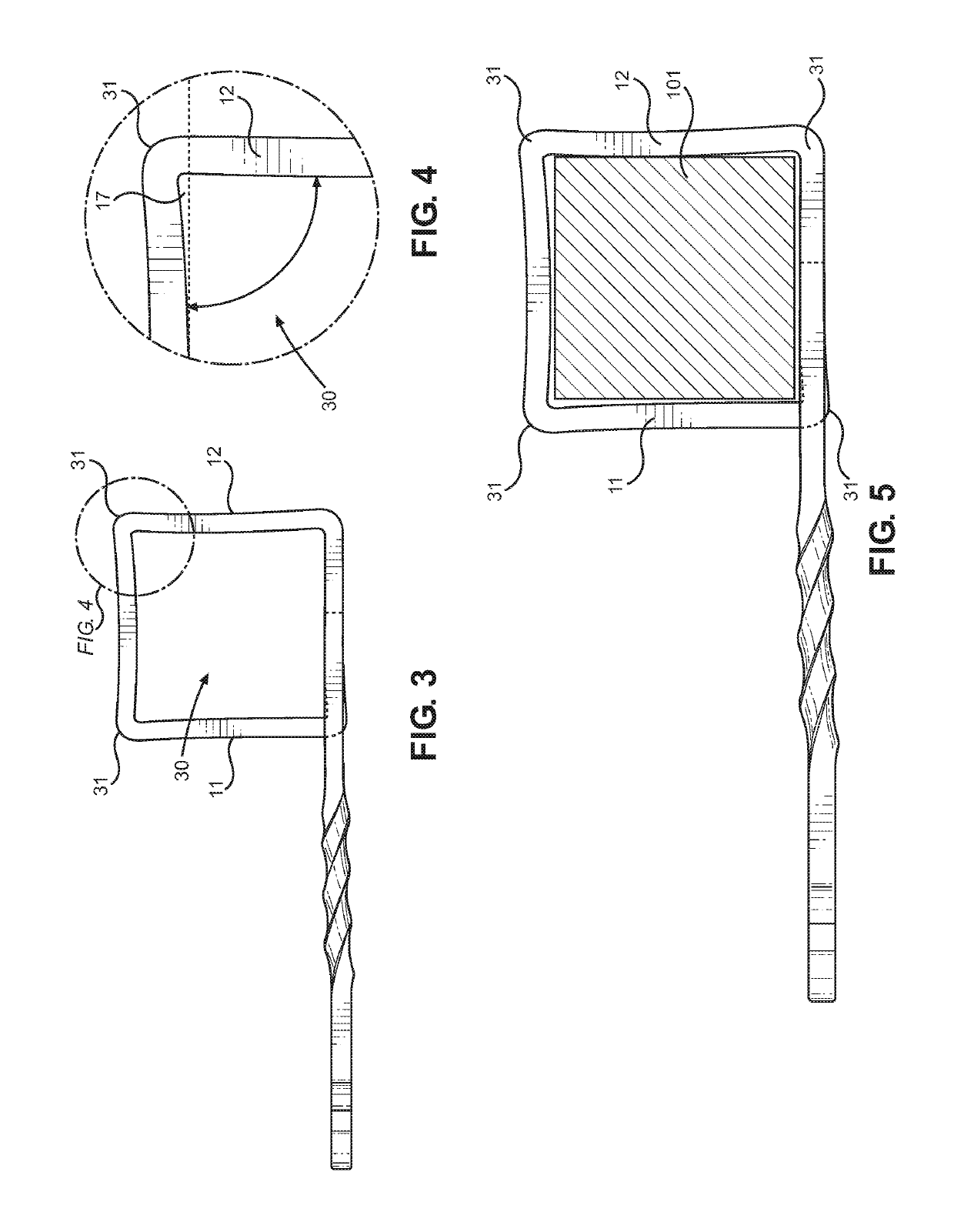
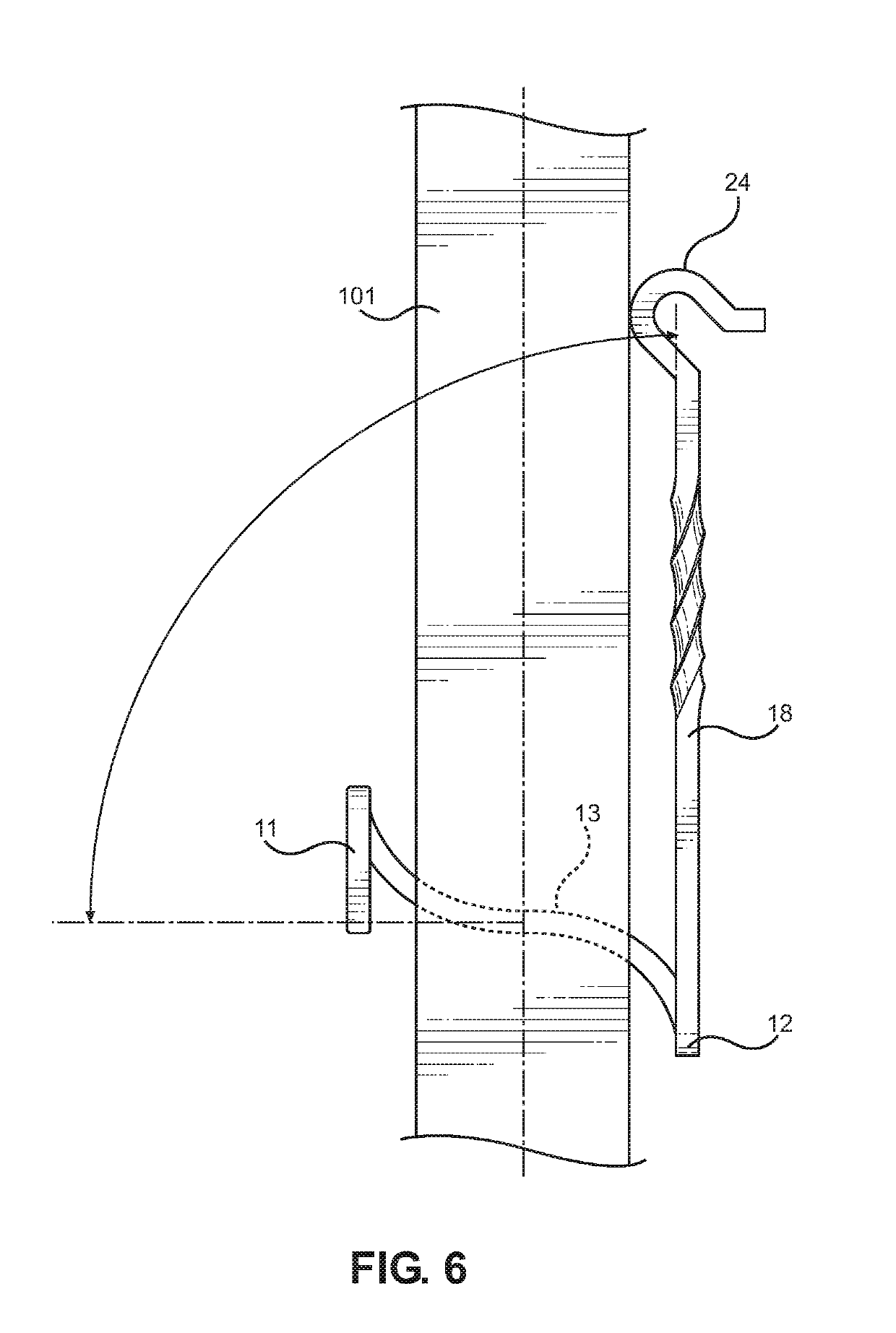
[0021]Reference is made herein to the attached drawings. Like reference numerals are used throughout the drawings to depict like or similar elements of the cantilevered support hanger. For the purposes of presenting a brief and clear description of the present invention, the preferred embodiment will be discussed as used for securing to a vertically oriented square post without the use of fasteners in order to hang objects therefrom. The figures are intended for representative purposes only and should not be considered to be limiting in any respect.

[0022]Referring now to FIGS. 1 and 2, there is shown a perspective view of an embodiment of the cantilevered screwless hanger and a side elevation view of an embodiment of the cantilevered screwless hanger, respectively. The cantilevered screwless hanger 10 includes an elongated member 18 comprising a support assembly 27 disposed on a first end 19 thereof. In the shown embodiment, the elongated member 18 further includes a hanging device ...


PUM


Abstract

A cantilevered screwless hanger. The cantilevered screwless hanger includes an elongated member having a support assembly disposed on a first end thereof. In some embodiments, the elongated member includes a hanging device on a second end thereof. The support assembly includes a lower U-shaped member, a connecting member extending upwardly therefrom, and an upper U-shaped member connected to the connecting member. The lower U-shaped member is oriented opposite the upper U-shaped member, such that a first opening defined by the lower U-shaped member is oriented opposite a second opening defined by the upper U-shaped member. The support assembly is adapted to removably secure the cantilevered screwless hanger to an elongated structure comprising a square cross-section without the use of additional fasteners, such that the support structure is not damaged during installation of the cantilevered screwless hanger.

Description

CROSS REFERENCE TO RELATED APPLICATIONS[0001]This application claims the benefit of U.S. Provisional Application No. 62 / 571,318 filed on Oct. 12, 2017. The above identified patent application is herein incorporated by reference in its entirety to provide continuity of disclosure.BACKGROUND OF THE INVENTION[0002]The present invention relates to cantilevered support devices. More specifically, the present invention provides a cantilevered screwless hanger that can be utilized to support objects from a vertically oriented square post without the use of fasteners.[0003]Many individuals utilize support devices such as hooks to hang objects outdoors, such as a flag, a potted plant, or the like. Support hooks are often secured to a structure via fasteners such as nails or screws. The use of such fasteners requires tools that the individual may not have available at their disposal, such as a drill. The use of fasteners to hang a support hook can also cause damage to the structure to which t...

Claims


Application Information

Patent Timeline
IPC IPC(8): F16M13/02A47G7/04
CPCF16M13/022A47G7/044G09F17/00A47G7/045
Inventor HAWK, CHRISTOPHER
Owner HAWK CHRISTOPHER
Why Eureka
Eureka Blog
Learn More