Fuel Container

a technology for fuel containers and portable containers, applied in the direction of liquid transfer devices, packaging foodstuffs, packaged goods, etc., can solve the problems of impracticality or impossible, impracticality or burdensome to transport such devices to a gas station to be filled, and the portability of fuel containers is often susceptible to spillag

Active Publication Date: 2019-04-11
FUELHOSS LLC
View PDF0 Cites 3 Cited by
  • Summary
  • Abstract
  • Description
  • Claims
  • Application Information

AI Technical Summary

Benefits of technology

[0011]Preferably, different volume PFCs share a similar profile, differing only in width. In this manner, the components other than the blow molded body can be utilized in the different volume PFCs to provide economies of scale in production.
[0013]According to one aspect of the invention, an additional safety feature built into the PFC prevents fuel from entering the pour spout when the spout is in a full “closed” storage position. This is achieved by incorporating a rotational valve into the internal components. Additionally, a diaphragm may be provided.
[0017]Other end user benefits to the new PFC design include an easy-to-read fill line on a side of the container, vertical and horizontal stackability, and a modular design so that containers of different volumes can stack safely so that smaller volume containers can stack on top of larger containers. For example, a 2 gallon PFC can safely stack onto a 5 gallon PFC for safe storage.

Problems solved by technology

Portable fuel containers are generally used to transport fuel from a fuel station pump to a device when it would be impractical or impossible to directly access the fuel station pump with the device.
For example, one may desire to fill gasoline engine powered devices such as landscaping equipment, all-terrain vehicle, off-road vehicle, and so on with fuel, but it is impractical or burdensome to transport such devices to a gas station to be filled.
However, portable fuel containers are often susceptible to spillage when dispensing fuel as the result of imprecise human operation and the difficulty in handling heavy containers (e.g. when users tilt the containers to drain them).
Additionally, it is typically difficult to empty all the fuel in conventional portable fuel containers, which can result in wasted fuel.
Often, the activation mechanism is difficult to use when holding a container steady with liquid disposed therein and simultaneously pouring the contents from the container into a desired location, such as a fuel tank.

Method used


Image

  • Fuel Container
  • Fuel Container
  • Fuel Container

Examples


Embodiment Construction

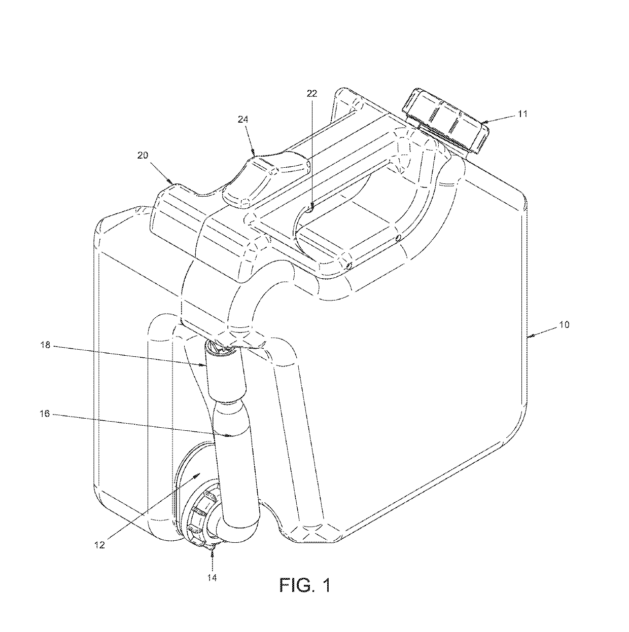
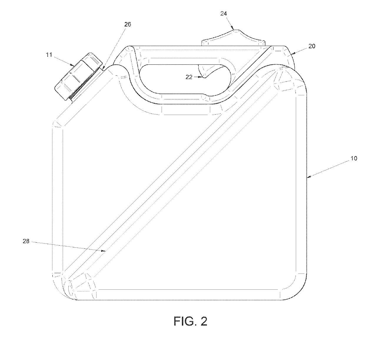
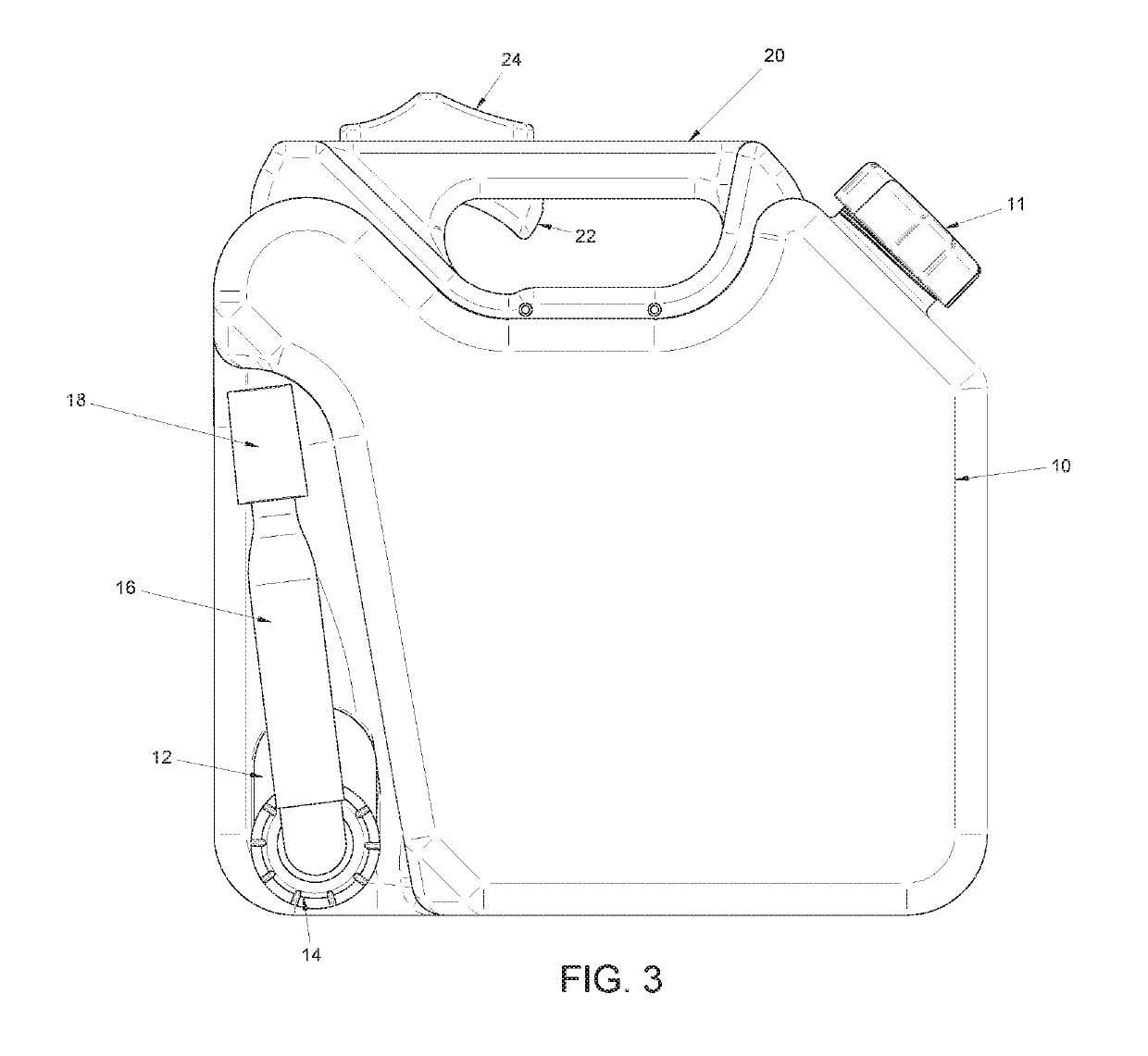
[0047]FIGS. 1-6 are views of a Portable Fuel Container (PFC). FIG. 1 is a front perspective view of the PFC. The PFC has a body 10. Typically the body 10 is blow molded as a single element. An injection molded spout plate 12 is affixed to the body 10. Preferably, high density polyethelene (HDPE) or the like is used for the various molded components. Preferably, the spout plate 12 is attached to the body 10 by an ultrasonic welded seam. Alternatively, the spout plate 12 is attached to the body 10 by adhesives or the like. In one embodiment, the spout plate is formed with the body 10. According to one aspect of the invention, the spout plate 12 is comolded with the body 10. The spout plate 12 is arranged at a lower edge of the body 10. A spout 16 is coupled to the body 10 at the spout plate 12. The spout 16 is locked in place by a lock nut 14. The spout 16 is configured to rotate from a storage position shown in FIG. 1 to a use position, shown for example in FIG. 16. In one embodiment...


PUM


Abstract

A fluid container having a body, a handle arranged in a top section of the body, a flow trigger in the handle, and a safety trigger that interacts with the flow trigger and prevents activation of the flow trigger. A vent assembly is arranged in the body and is configured to b activated by the safety trigger to vent the body. A spout assembly is movably coupled to the body and rotates between a use position and a storage position. A first valve opens as the spout assembly is moved from the storage position to the use position and a second valve is arranged upstream of the first valve to control fluid flow into the spout assembly. A linkage mechanism is arranged between the flow trigger and the second valve and configured to open the second valve when the flow trigger is activated and the safety trigger is released.

Description

BACKGROUND OF THE INVENTION1. Field of the Invention[0001]This invention generally relates to portable containers for liquids. More particularly, the invention relates to a portable container that includes a pour spout. Specifically, the invention relates to a pour spout for a portable fuel container that includes a venting valve, and a valve assembly for sealing the spout when the container is not in use.2. Description of the Related Art[0002]Portable fuel containers are generally used to transport fuel from a fuel station pump to a device when it would be impractical or impossible to directly access the fuel station pump with the device. For example, one may desire to fill gasoline engine powered devices such as landscaping equipment, all-terrain vehicle, off-road vehicle, and so on with fuel, but it is impractical or burdensome to transport such devices to a gas station to be filled. On the other hand, portable fuel containers may be filled up at a gas station pump and then trans...

Claims


Application Information

Patent Timeline
Patent Type & Authority Applications(United States)
IPC IPC(8): B67D7/04B65D1/20B65D21/02B65D25/46B67D7/00
CPCB67D7/04B65D1/20B65D21/0204B65D25/46B67D7/005B65D85/84B65D2205/00B65D25/38
Inventor SHAW, TIMOTHY JAMES
Owner FUELHOSS LLC
Why Eureka
Try Eureka