
Optical beam steering devices having polygonal reflectors therein

a technology of optical beams and steering devices, which is applied in the direction of shafts, bearings, rotary bearings, etc., can solve the problems of incompatibility with applications where electrical power is required, large electrical power consumption, and the back and forth oscillatory nature of the device is not as energetically favorable with respect to a technology that continuously rotates

Active Publication Date: 2019-04-04
MIRADA TECH INC
View PDF3 Cites 4 Cited by
  • Summary
  • Abstract
  • Description
  • Claims
  • Application Information

AI Technical Summary

Benefits of technology

The patent describes a device that uses a polygonal reflector to focus light. The reflector is embedded within a smooth-surfaced optically transparent encasement and is stabilized by a mechanical coupling to a container. The device also includes fluid channels that support the reflector's movement as it rotates within the liquid. The technical effect of this device is improved focus and stability during use.

Problems solved by technology

It has been observed that galvanometer-based technologies consume significant electrical power under operation, making them incompatible for applications where electrical power is constrained.
The electrical power consumption is largely a function of the mass of the mirror being moved, and the fact that significant energy is expended to accelerate the mirror to a position, then decelerate the mirror to stop at the desired position.
The back and forth oscillatory nature of the devices is not as energetically favorable with respect to a technology that continuously rotates.
It has been further observed that the mechanical complexity of the construction of galvanometer-based technologies limits the ability to miniaturize this technology to achieve low cost.
It has been observed that voice coil mirror systems consume significant amounts of electrical power, and given that they have multiple parts including fine electrical windings, they are difficult to miniaturize at low cost.
The electrical power consumption is largely a function of the mass of the mirror being moved, and the fact that significant energy is expended to accelerate the mirror to a position, then decelerate the mirror to stop at the desired position.
The back and forth oscillatory nature of the devices is not as energetically favorable with respect to a technology that continuously rotates.
It has been observed that electrostatic actuation results in small movements, which in turn, even when mechanically amplified into larger angles, results in modest angles of motion in the mirror.
It has been observed that electrothermal actuators are relatively slow, and do not produce high speed precision motion relative to other technologies.
Additionally, they typically consume significant electrical power in order to generate the high temperatures in regions of the actuators.
In order to produce high temperatures and the associated thermal expansion more efficiently, some such product package the actuators in vacuum or low thermal conductivity gasses, adding to the cost of the product.
It has been observed that traditional manufacturing methods such as used in galvanometers and voice coil technologies do not scale down to small sized cost effectively.
MEMS manufacturing technology has the capability of forming high precision mechanical structures at sub-millimeter scales, but it has been observed that the beam steering devices manufactured using MEMS fabrication, even when produced on large silicon wafer, do not achieve sufficiently low cost in high production volume.
This is generally due to the complexity of each manufacturing step, the number of manufacturing steps, and the complex equipment typically required.
This approach is energetically favorable with respect to the oscillatory technologies where a mirror is accelerated and decelerated back and forth, but lacks the ability for the mirror to maintain a fixed position if required.
It has been observed that polygonal mirror scanners that use ball bearing based bearing systems can be susceptible to dust and moisture from the environment and under continuous operation, and typically have a lifetime for reliable operation that is under two years.
Ball bearing based bearing systems are more robust under mechanical forces and vibration than alternative air bearings, but also can be damaged due to external forces, gravitational changes, and vibrations.
It has also been observed that polygonal mirror scanners that use air bearings have long lifetimes when used in stationary, low vibrational environments, but are highly susceptible to shock and vibration that can result in catastrophic failure.
When subjected to significant acceleration, the suspended moving mass can bridge that gap, colliding with the fixed surfaces and initiate an imbalance in the high speed rotation, leading to catastrophic failure.

Method used


Image

  • Optical beam steering devices having polygonal reflectors therein
  • Optical beam steering devices having polygonal reflectors therein
  • Optical beam steering devices having polygonal reflectors therein

Examples


Embodiment Construction

[0047]Reference will now be made in detail to embodiment(s) of the present invention. While the invention will be described in conjunction with the embodiment(s), it will be understood that they are not intended to limit the invention to these embodiments. On the contrary, the invention is intended to cover alternatives, modifications and equivalents, which may be included within the spirit and scope of the invention as defined by the appended claims.

[0048]Furthermore, in the following detailed description of the present invention, numerous specific details are set forth in order to provide a thorough understanding of the present invention. However, it will be recognized by one of ordinary skill in the art that the present invention may be practiced without these specific details. In other instances, well known methods, procedures, and components may not have been described in detail as not to unnecessarily obscure aspects of the present invention.

[0049]The present invention enables...


PUM


Abstract

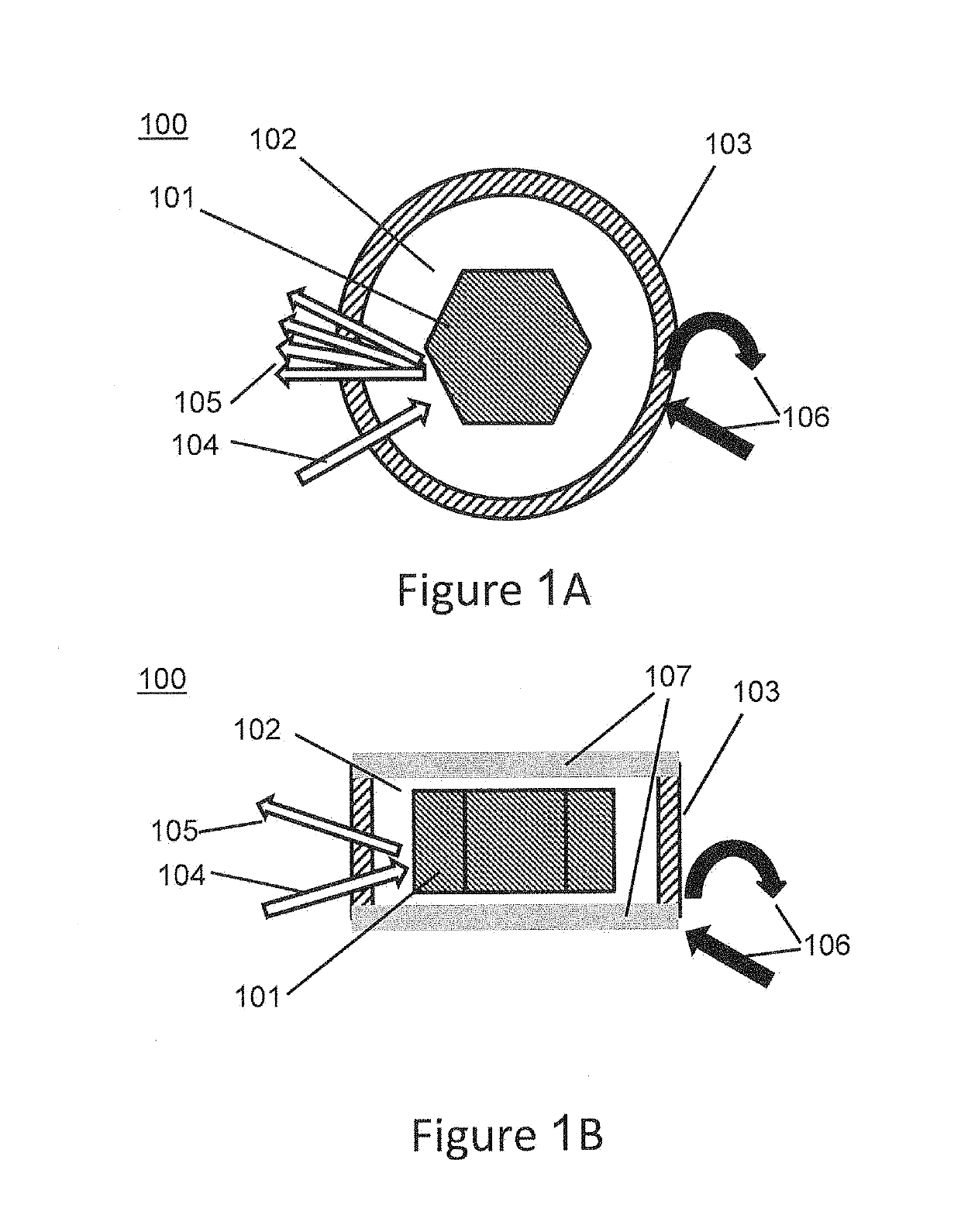
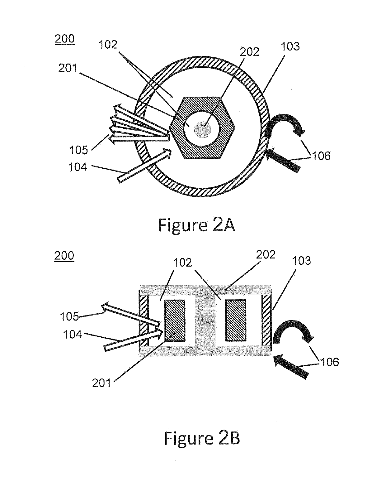
An optical beam steering device includes an at least partially optically transparent container having a polygonal reflector therein that is at least partially surrounded within the container by an optically transparent liquid. The polygonal reflector may be configured to have a center of mass, which is equivalent to its geometric center. In addition, the polygonal reflector may be configured so that a difference between an effective density of the polygonal reflector and a density of the optically transparent liquid is preferably less than about 2.1 grams per cubic centimeter. More preferably, the polygonal reflector and the optically transparent liquid may be collectively configured to be neutrally buoyant relative to each other within the container.

Description

REFERENCE TO PRIORITY APPLICATIONS[0001]This application is a continuation-in-part of U.S. application Ser. No. 15 / 897,977, filed Feb. 15, 2018, which claims priority to U.S. Provisional Application Ser. No. 62 / 600,577, filed Feb. 24, 2017, U.S. Provisional Application Ser. No. 62 / 603,175, filed May 20, 2017 and U.S. Provisional Application Ser. No. 62 / 577,329, filed Oct. 26, 2017. This application is also a continuation-in-part of International Patent Application No. PCT / US2018 / 019132, filed Feb. 22, 2018; International Patent Application No. PCT / US2018 / 033363, filed May 18, 2018; and International Patent Application No. PCT / US2018 / 057531, filed Oct. 25, 2018. The disclosures of each of these patent applications are hereby incorporated herein by reference.FIELD OF THE INVENTION[0002]The invention relates to directing beams of light in specific directions using movable reflective surfaces, and in a robust, reliable manner.BACKGROUND OF THE INVENTION[0003]Directing beams of light in ...

Claims


Application Information

Patent Timeline
IPC IPC(8): G02B5/09G02B26/12
CPCG02B5/09G02B26/121F16C17/00G02B1/06
Inventor MINER, ANDREW CARLMAPEL, JONATHAN KING
Owner MIRADA TECH INC
Learn More