
Gas turbine

Active Publication Date: 2019-03-28
DOOSAN HEAVY IND & CONSTR CO LTD
View PDF3 Cites 2 Cited by
  • Summary
  • Abstract
  • Description
  • Claims
  • Application Information

AI Technical Summary

Benefits of technology

The present patent aims to address the problem of flow separation in gas turbines, which leads to reduced efficiency and increased pressure loss. It proposes a solution to minimize these losses and stabilize the flow of combustion gas by optimizing the shape of the strut, the part of the gas turbine that helps to direct the flow of gas. This approach can reduce flow congestion and improve the efficiency of the gas turbine.

Problems solved by technology

Therefore, it has no mutually frictional parts such as a piston and cylinder, thereby consuming an extremely small amount of lubricating oil and reducing the operational amplitude unlike the reciprocating mechanism, which results in high speed operation.
Therefore, the bearing support has a problem of easily fracturing or being damaged.
For this reason, the coupling points of the struts to the inner and outer casings, as well as the struts themselves, suffer a concentration of mechanical stress, which can result in damage to the support structure of the bearings.
In addition, there is a difficulty in designing the support structure and the rotor, such as to avoid resonance problems.

Method used


Image

  • Gas turbine
  • Gas turbine
  • Gas turbine

Examples


first embodiment

[0078]Struts provided in the gas turbine according to the present disclosure will be described in more detail with reference to FIGS. 2 and 3.

[0079]Referring to FIGS. 2 and 3, the gas turbine according to the first embodiment of the present disclosure includes a cylinder-shaped outer casing 110 having a predetermined thickness and length, and an inner casing 120 concentrically disposed inside the outer casing 110 and having a predetermined thickness and length.

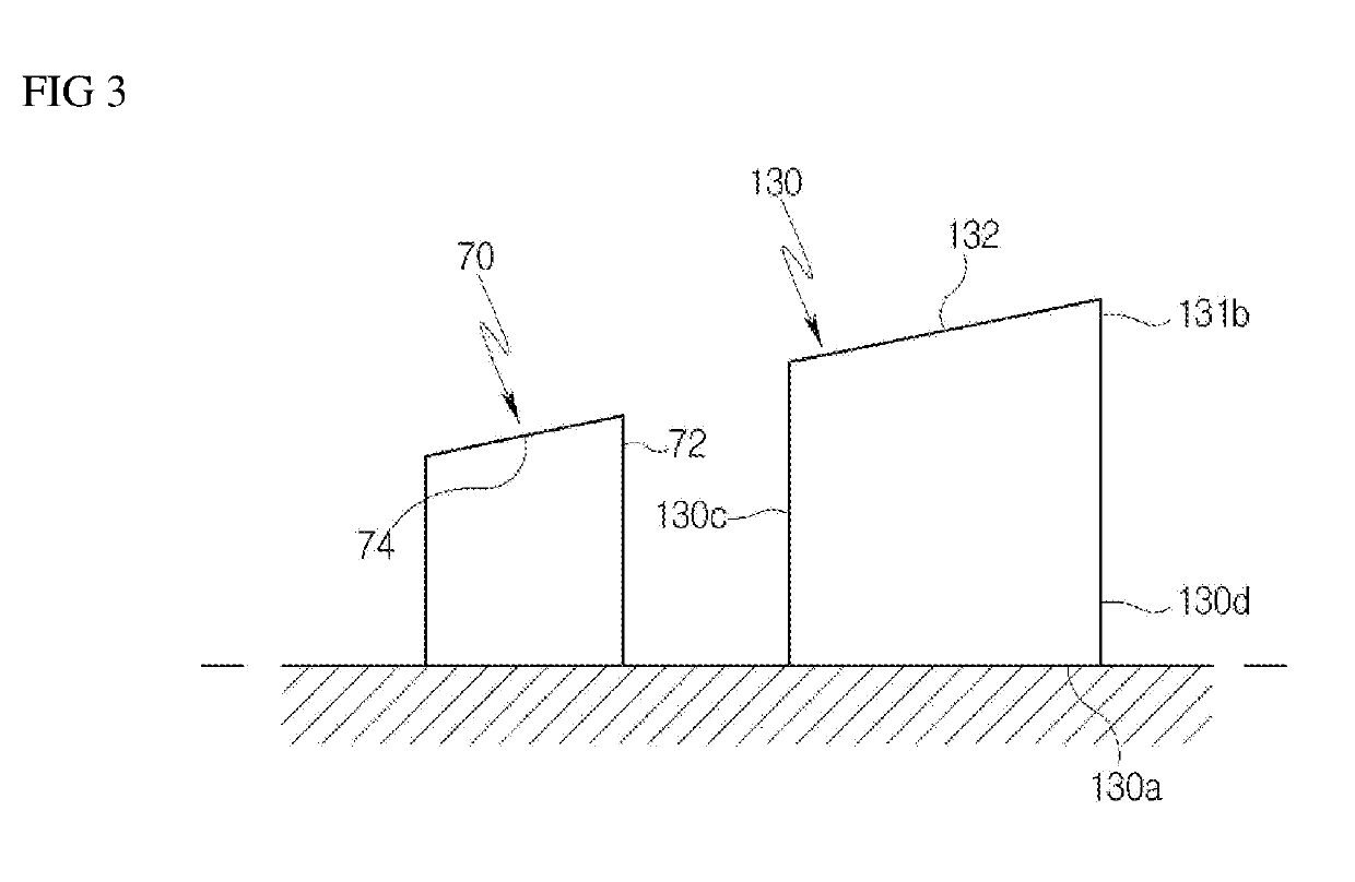
[0080]The struts 130 are formed in the shape of an airfoil extending generally in the axial direction of the inner casing 120 and the outer casing 110, as shown in the drawings. Each of the struts 130 is provided between the outer casing 110 and the inner casing 120 and has opposite ends respectively fixed to the surface of the outer casing 110 and the surface of the inner casing 120.

[0081]The struts 130 are provided with inclined portions 132 that are inclined toward the rear sides of the struts to guide the movement of the c...

second embodiment

[0106]A gas turbine according to the present invention will be described with reference to FIGS. 6 to 9.

[0107]Referring to FIGS. 6 to 9, according to the second embodiment, the gas turbine includes an outer casing 110 having an annular shape, an inner casing 120 disposed inside the outer casing, and a plurality of struts 130, each having a first end and a second end fixed to an outer surface of the inner casing 120 and an inner surface of the outer casing 110, respectively, in which each strut 130 has an inclined portion 132 at a tip 131b thereof, the inclined portion 132 being inclined outward from a leading end to a trailing end of the tip 131b, and in which an angle of attack of a leading edge 130c of the strut 130 varies over the entire span S of the strut 130, which ranges from a hub 131a to the tip 131b.

[0108]In this embodiment, the angle of attack of the strut 130 can be changed to induce an optimum flow of the combustion gas according to the position, thereby minimizing flo...


PUM


Abstract

A gas turbine includes an outer casing having an annular shape; an inner casing disposed inside the outer casing; and a plurality of struts, each strut having a first end fixed to an outer surface of the inner casing, a second end fixed to an inner surface of the outer casing, and an inclined portion for guiding a flow of combustion gas, wherein the inclined portion is inclined from a front side to a rear side.

Description

CROSS REFERENCE TO RELATED APPLICATIONS[0001]The present application claims priority to Korean Patent Application No. 10-2017-0125159, filed Sep. 27, 2017, the entire contents of which is incorporated herein for all purposes by this reference.BACKGROUND OF THE DISCLOSURE1. Field of the Disclosure[0002]The present disclosure relates to a gas turbine having a strut having a structure being capable of minimizing separation of fuel gas passing through the strut.2. Description of the Background Art[0003]Generally, a turbine refers to a rotary mechanical device that extracts energy from a fluid flow, such as water, vapor, air, or gas, and converts it into useful mechanical work. A turbine is a turbo-machine with at least one moving part, called a rotor assembly, which is a shaft with blades or vanes attached. Moving fluid is ejected to impact the blades or vanes and to cause a reaction force of the blades or vanes, which moves the rotor assembly at high speed.[0004]Turbines are categorize...

Claims


Application Information

Patent Timeline
IPC IPC(8): F01D25/26F01D25/28F02C7/20
CPCF01D25/26F01D25/28F02C7/20F05D2220/32F05D2240/14F05D2260/30F01D5/145F01D25/162F05D2250/38F05D2250/314F01D9/02
Inventor JUNG, JIN SOL
Owner DOOSAN HEAVY IND & CONSTR CO LTD
Learn More