Log collection device, log generation device, and log collection method

a technology of log generation device and log collection device, which is applied in the field of log collection device, log generation device, and log collection method, can solve the problems of log collection device, log message consumption, log collection device, etc., and achieve the effect of suppressing the increase in the processing load of the log generation device and low load

Active Publication Date: 2019-03-21
PANASONIC INTELLECTUAL PROPERTY MANAGEMENT CO LTD
View PDF3 Cites 6 Cited by
  • Summary
  • Abstract
  • Description
  • Claims
  • Application Information

AI Technical Summary

Benefits of technology

[0012]According to this disclosure, it is possible to transmit the text log with a low load in a case where the increase in the processing load of log generation device is suppressed.

Problems solved by technology

However, since the text format log message (hereinafter referred to as “text log”) has a relatively large data size, consumption of communication resources between log generation device and a device that receives the log message (hereinafter referred to as “log collection device”) becomes a problem.
In particular, in a case where one log collection device collects log messages from a large number of log generation devices via a common communication line, in a case where a communication band between the log generation device and the log collection device is narrow, or in a case where a transmission amount of the log message is large, the performance of the entire system may be degraded.
In addition, in order to avoid such degradation in performance, the number of log generation devices that can be managed by one log collection device is limited.
By the way, depending on log generation device, there is a case where it is difficult to have sufficient process capability to perform the lexicographic compression.

Method used


Image

  • Log collection device, log generation device, and log collection method
  • Log collection device, log generation device, and log collection method
  • Log collection device, log generation device, and log collection method

Examples


modification example

of this Embodiment

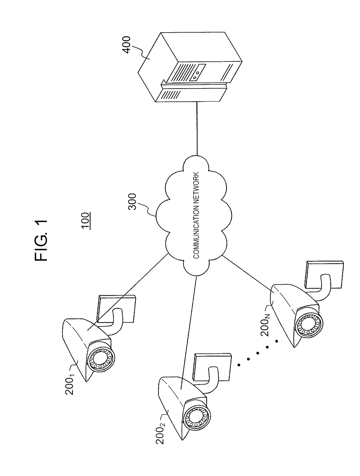
[0133]Log generation device 200 is not limited to the monitoring camera but may be other various devices that generate text logs.

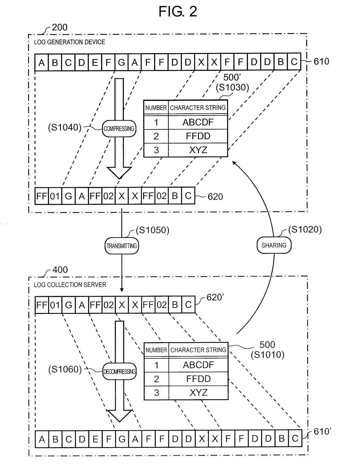
[0134]In addition, the contents, format, and the generation method of the compressed dictionary are not limited to the example described above, and various compression techniques may be used as long as the various techniques can efficiently compress and decompress the original text log in a recoverable manner.

[0135]In addition, log collection server 400 is not necessarily required to manage dictionary sharing information indicating which compressed dictionary has been sent to which log generation device 200 (which compressed dictionary is used by each log generation device 200). For example, in a case where log generation device 200 transmits information indicating which compressed dictionary is being used and the compression process is performed to log collection server 400, log collection server 400 may determine the compressed dictiona...


PUM


Abstract

There is provided a log collection device including: a log receiver that receives a text log from a log generation device; a dictionary generator that generates a compressed dictionary for performing text compression based on the received text log; a dictionary transmitter that transmits the generated compressed dictionary to the log generation device and instructs performing of the compression process using the compressed dictionary on the text log transmitted after the transmission of the compressed dictionary; and a decompression processor that performs a decompression process using the compressed dictionary on the text log received after transmission of the compressed dictionary.

Description

TECHNICAL FIELD[0001]This disclosure relates to a log collection device that receives / transmits text logs, a log generation device, and a log collection method.BACKGROUND ART[0002]A device (hereinafter referred to as “log generation device”) that generates a log message indicating generation of a predetermined event and transmits the generated log message to another device is used in various fields. A monitoring camera that notifies a server of a central monitoring center when a suspicious person is detected is an example of such a log generation device.[0003]As a data format of the log message, for example, a text format is adopted. Syslog, which describes a log message in ASCII, is an example of such a log message.[0004]However, since the text format log message (hereinafter referred to as “text log”) has a relatively large data size, consumption of communication resources between log generation device and a device that receives the log message (hereinafter referred to as “log col...

Claims


Application Information

Patent Timeline
Patent Type & Authority Applications(United States)
IPC IPC(8): H03M7/30G06F11/34
CPCH03M7/3088G06F11/3476G06F11/30G06F11/34G06F11/3082
Inventor OZAKI, MINORU
Owner PANASONIC INTELLECTUAL PROPERTY MANAGEMENT CO LTD
Why Eureka
Try Eureka