
Device for printing closures of closed containers

a technology for printing closures and containers, applied in typewriters, packaging, labelling machines, etc., can solve the problems of minor deviations in the shape of actual containers, containers produced are not rotationally symmetrical, and the printing of closures can be very flawed

Inactive Publication Date: 2019-03-21
KRONES AG
View PDF5 Cites 4 Cited by
  • Summary
  • Abstract
  • Description
  • Claims
  • Application Information

AI Technical Summary

Benefits of technology

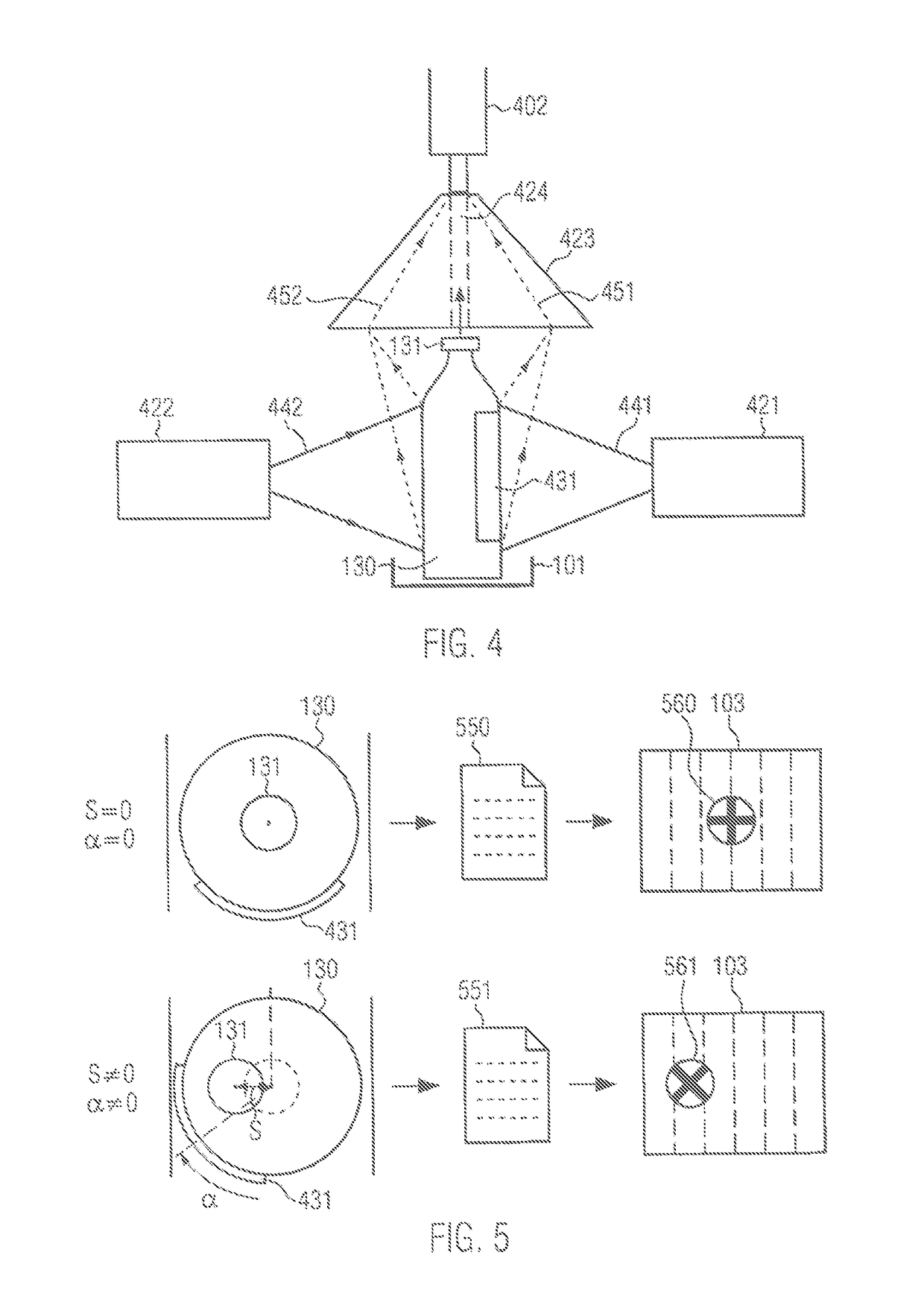
The patent describes a printing system that is able to print closure images on containers, even if they are not perfectly shaped. The system compensates for any minor deviations in the container shape and ensures reliable printing of each container. The printing unit can be stationary and the software-based modification of the print image can be faster than a shift of the printing unit. The system can use information on the container that is visible to the final consumer to increase customer acceptance. The optical body of the system is designed to pass on information about the container and simultaneously the position of the closure without any potentially disturbing optical effects. The software-based manipulation of the print image can sometimes be faster than the changing of the position of the printing unit, which allows for individual adaptation of the ejection of the printing ink for each container.

Problems solved by technology

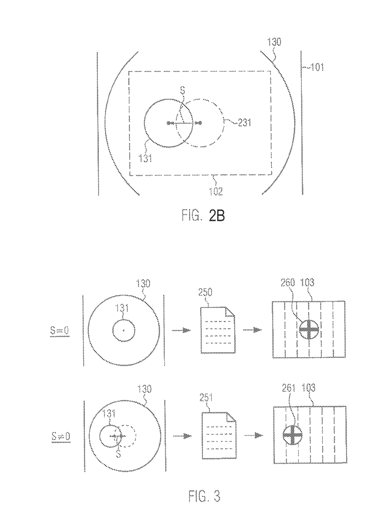
Especially in the case of containers made of glass, which are for example provided with a crown cap, the production process of the glass bottles may cause minor deviations in the shape of the actual containers from the ideal shape, so that the containers produced are not rotation-symmetrical.
As a consequence, the printing of the closure can be very flawed.
Corresponding problems may also arise in containers made of plastics, particularly PET.

Method used


Image

  • Device for printing closures of closed containers
  • Device for printing closures of closed containers
  • Device for printing closures of closed containers

Examples


Embodiment Construction

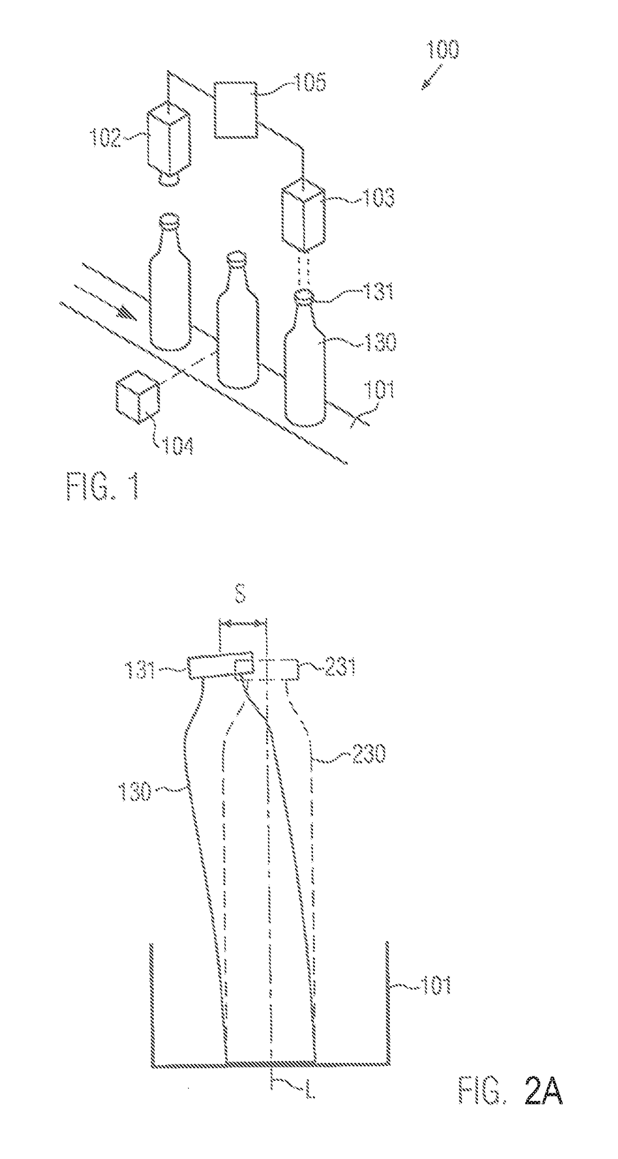
[0035]FIG. 1 shows a device 100 for printing closures 131 of closed containers 130. The device comprises a transport section 101 in which the closed containers 130 are transported along a transport direction (arrow). Thus the transport section defines a transport direction for the containers 130. The transport section may be configured as a conveyor belt. Other embodiments, for example transportation of the containers on stands, are also conceivable. The transport section need not be made linear, but may also be provided as a part of a machine configured as a rotary machine with a plurality of container holders.

[0036]The device 100 can be part of a container treatment system for treating containers. In addition to the device 100, the container treatment system can comprise further container treatment machines, in particular a filler, a closer, and a labeling machine. All of these container treatment machines may be arranged upstream of the device 100. However, one or more may also b...


PUM


Abstract

A device for printing closures of closed containers, comprising a transport section for transporting the containers, wherein a detection unit and a printing unit for printing the closure of a container are arranged behind one another in the transport direction and the detection unit can individually determine the position of the closure transversely with respect to the transport direction for each container and can transmit a signal which is indicative of the position to a control unit which is assigned to the detection unit and the printing unit. The control unit is designed to control the printing unit to apply printing ink to the closure in order to print the closure according to its position. Also disclosed is a corresponding method.

Description

[0001]The present invention refers to a device and a method for printing closures of closed containers.PRIOR ART[0002]It is known from the prior art that closures of containers are provided with print images.[0003]With respect to containers equipped with labels it is known from DE 10 2006 019 441 A1 that the imprint is applied to the closure on the basis of the random orientation (rotation) of the label provided on the container. The position of the containers, which are for example transported in a transport starwheel, is known at any time and only their rotational position or the position of the label relative to the printing head, which is to apply the image to the closure, has to be determined for each container.[0004]Furthermore, it is known from WO 2015 / 011663 A1 that closures of containers are printed taking into account the distance of the containers from one another in a transport device. For this purpose the infeed of each container into the corresponding printing station ...

Claims


Application Information

Patent Timeline
IPC IPC(8): B65C9/46
CPCB65C9/46B41J11/002B41J3/4073B67B3/006B41J11/008B41J11/0095
Inventor LINDNER, PETER
Owner KRONES AG
Learn More