
Apparatus and method for promoting wound healing

a technology of apparatus and wounds, applied in the field of medical devices, can solve the problems of inability to deliver cardiosynchronized sequential or gradient compression, inability to transfer the effect of lowering pressure on the venous end of the capillary bed, and inherently very limited design mechanisms, so as to reduce tissue pressure, enhance normal arterial flow, and reduce the volume of venous and interstitial fluid of the limb.

Pending Publication Date: 2019-03-21
SYNCARDON LLC
View PDF0 Cites 8 Cited by
  • Summary
  • Abstract
  • Description
  • Claims
  • Application Information

AI Technical Summary

Benefits of technology

The present invention provides a novel apparatus for variable pressure therapy using a new waveform called the sequential gradient arterial pulse wave-synchronized waveform. This waveform is different from other existing pulsatile or sequential waves in that it is delivered in a way that mimics natural arterial flow. Compared to prior art devices, the present invention uses a smaller number of inflatable cells and delivers the waveform in a more distal-to-proximal fashion, with each heartbeat. This approach enhances the natural pattern of arterial blood flow and reduces tissue pressure, thus improving the efficiency of the therapy.

Problems solved by technology

Such a design mechanism is however, inherently very limited in its ability to enhance arterial inflow, for the following reason.
So the ability to transfer the effects of lower pressure on the venous end of the capillary bed, through that bed to the arterial side is very limited.
None of the prior art methods or apparatus have the ability to deliver cardiosynchronized sequential or gradient compression from proximal to distal limb aspects to mimic and enhance normal arterial flow or to provide compression in a manner that is guided by distal limb flow to maximize delivery to the most ischemic aspect of the limb or to document tissue healing with infrared or other detection / display methods.

Method used


Image

  • Apparatus and method for promoting wound healing
  • Apparatus and method for promoting wound healing
  • Apparatus and method for promoting wound healing

Examples


Embodiment Construction

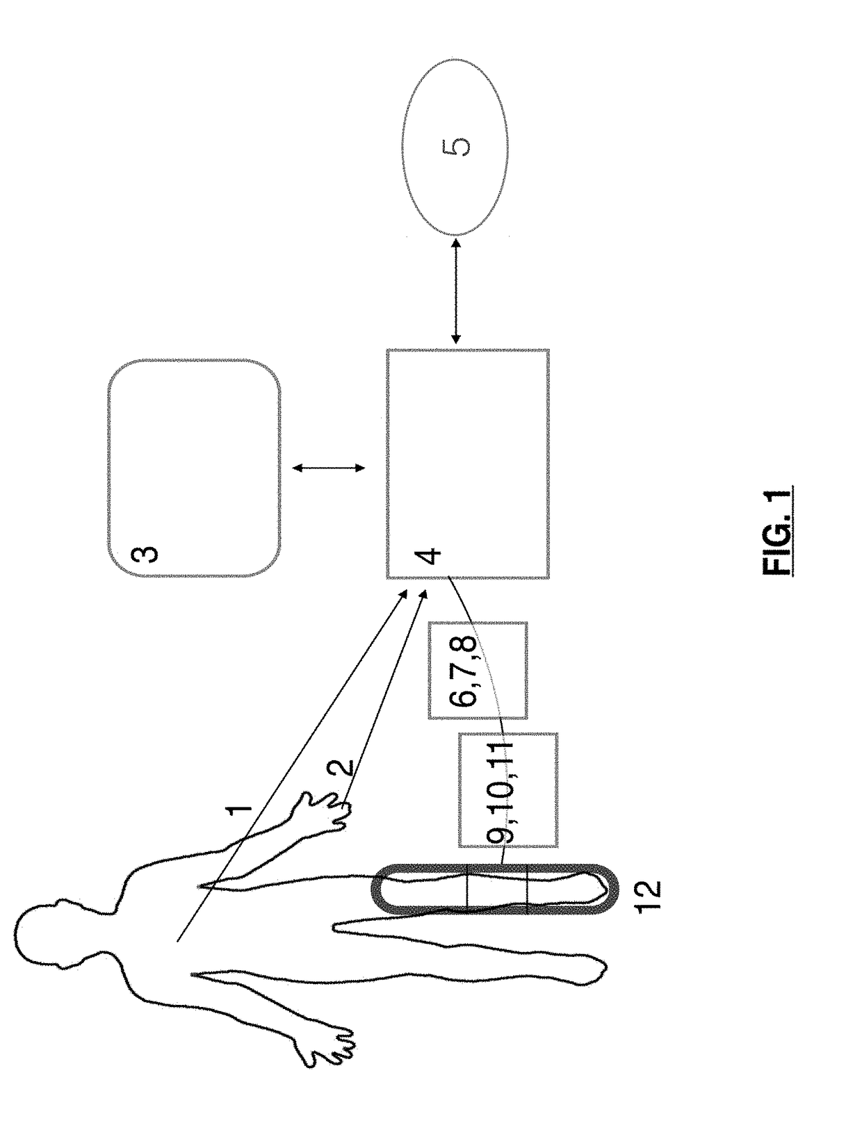
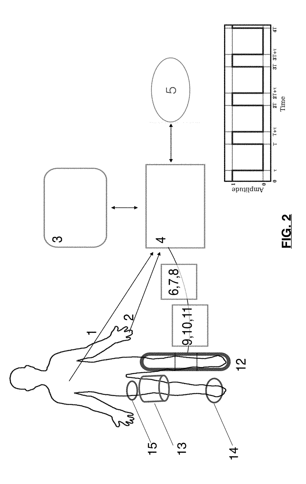
[0095]Referring to FIG. 1 in more detail, there is shown a simplified block diagram of apparatus. Below is identification of the components in FIG. 1.[0096]1. EKG signal[0097]2. PPG signal[0098]3. User interface[0099]4. Computing system[0100]5. External database[0101]6. Air Compressor[0102]7. Air Reservoir[0103]8. Inflation valves[0104]9. Conduits[0105]10. Circuitry controlling inflation valves[0106]11. Conduits[0107]12. Inflation Air Cells

[0108]FIG. 1 depicts a simplified overall design of the sequential compression system. The system compresses a limb at specific time intervals determined by inputs to the system. Inputs to the system include the EKG (1) and photoplethysmograph (PPG) waveform (2). EKG leads are attached to the body to supply the heart's pulsatile electrical signal, the EKG. At the distal end of the limb where the blood flow increase is desired, a PPG monitor is attached to detect pulsatile blood flow in the underlying tissue. A series of inflatable air cells (12) a...


PUM


Abstract

The system of the present invention uses inputs from EKG and PPG signals of blood flow at the end of the limb. To maximizes the PPG signal the system opens a series of valves in sequence, to inflate corresponding sequentially located cells wrapped circumferentially around the limb so that the most proximal cell inflates first, and its neighbor is inflated next. Fluid under pressure is supplied to the valves so that when opened, fluid enters the air cells and inflates them, compressing the underlying limb sequentially, from proximal to distal, to push blood downstream. Negative pressure wound treatment is used in combination with compression or separately therefrom.

Description

[0001]This application claims priority from Patent Cooperation Treaty Application PCT / US16 / 69040 filed Dec. 28, 2016.FIELD OF THE INVENTION[0002]The present invention relates generally to a medical device for applying negative or variable pressure to a portion of the body and particularly to methods and apparatus for the application of a sequential and gradient pulse wave for treating wounds that are difficult to heal or ‘livelihood limiting claudication and / or ischemic rest pain. An integral part of the present invention includes methods to determine blood flow and effects of treatments on tissue.BACKGROUND OF THE INVENTION[0003]Impaired circulation, i.e., decreased blood supply to tissue, is a common condition that can arise from several causes. For example, atherosclerosis of arteries as well as diabetic small vessel disease can cause ischemic tissue, leading to pain and / or non-healing wounds, a serious condition that can lead to limb loss. There are other disorders that can have...

Claims


Application Information

Patent Timeline
IPC IPC(8): A61H9/00A61B5/0402A61B5/00A61B5/0285A61B5/352
CPCA61H2201/5025A61H2201/5007A61H2201/5043A61H2201/5092A61H2201/5071A61H2209/00A61H2230/065A61B5/0402A61H9/0092A61H2230/201A61B5/4836A61B5/0285A61B5/4848A61H2201/0103A61H2201/5038A61H23/00A61B5/14551G16H40/63G16H20/30A61B5/318A61B5/02A61H23/04A63B7/02
Inventor KHURANA, VIKASSTEINBERG, JOEL
Owner SYNCARDON LLC
Learn More