
Buoyant structure

a buoyancy structure and floating technology, applied in vessel construction, special-purpose vessels, vessel ports, etc., can solve the problems of high cost of structures for deepwater applications, energy loss, pressure drop and production difficulties, and high cost of structures

Active Publication Date: 2019-03-14
JURONG SHIPYARD
View PDF3 Cites 3 Cited by
  • Summary
  • Abstract
  • Description
  • Claims
  • Application Information

AI Technical Summary

Benefits of technology

The present patent is about a new design for a floating production, storage and offloading (FPSO) vessel that improves its motion characteristics. The design takes into account various factors such as the draft, water plane area, and its draft rate of change, location of the center of gravity, metacentric height, frontal area, and shape on which winds, currents, and waves act, the system response of pipe and cables contacting the seabed acting as mooring elements, and the hydrodynamic parameters of added mass and damping. The design also allows for the addition of features that can be modified independently to provide the desired properties. The new design provides a more stable platform in deep water, reduces the need for long flowlines, cables, and umbilicals, and increases efficiency and efficiency of offshore operations.

Problems solved by technology

The extended lengths pose energy loss, pressure drop and production difficulties.
Costs of structures for deepwater applications are high and costs are frequently increased due to the foreign locations at which they are fabricated.
Other difficulties, associated with deepwater offshore operations, result from floating vessel motions which affect personnel and efficiencies especially when related to liquid dynamics in tanks.
The primary motion-related problem, associated with offshore petrochemical operations, occurs with large horizontal vessels in which the liquid level oscillates and provides erroneous signals to the liquid level instruments causing shutdown of processing and overall inefficiency for the operation.
If adverse weather conditions, such as a storm with significant wind speeds, occur during offloading, problems can occur due to movement of the tanker caused by wind and current forces acting on the tanker.

Method used


Image

  • Buoyant structure
  • Buoyant structure
  • Buoyant structure

Examples


Embodiment Construction

[0046]Before explaining the present apparatus in detail, it is to be understood that the apparatus is not limited to the particular embodiments and that it can be practiced or carried out in various ways.

[0047]Specific structural and functional details disclosed herein are not to be interpreted as limiting, but merely as a basis of the claims and as a representative basis for teaching persons having ordinary skill in the art to variously employ the present invention.

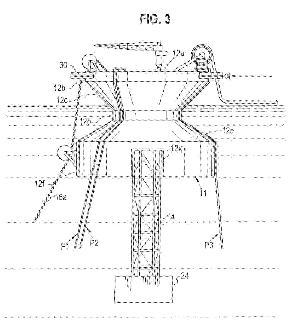
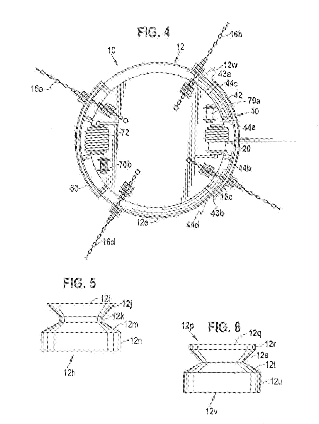
[0048]The present invention provides a floating platform, storage and offloading (FPSO) vessel with several alternative hull designs, several alternative center column design and a moveable hawser system for offloading, which allows a tanker to weathervane over a wide arc with respect to the FPSO vessel.

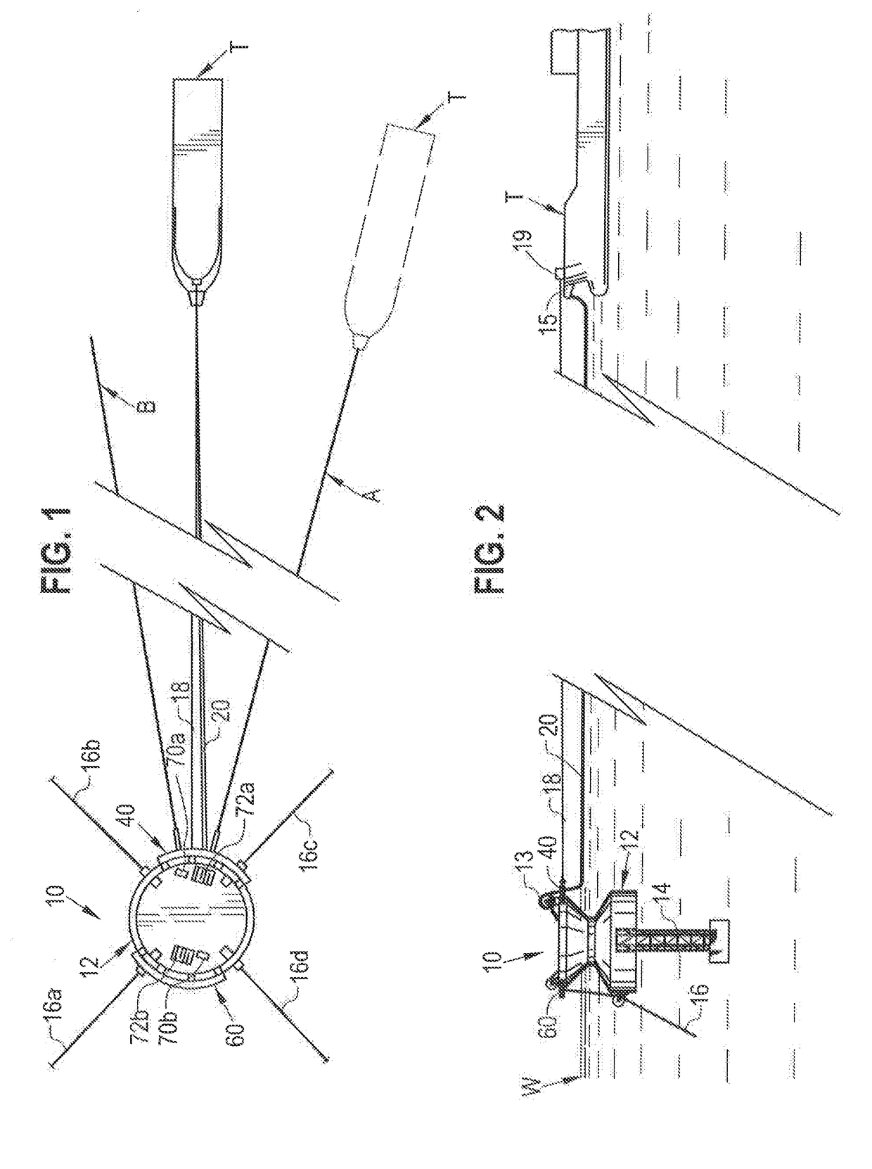
[0049]An FPSO vessel is shown in a plan view in FIG. 1 and in a side elevation in FIG. 2, according to the present invention. FPSO vessel 10 has a hull 12, and a center column 14 can be attached to hull 12 and extend down...


PUM


Abstract

A petroleum drilling, production, storage and offloading vessel having a hull, a main deck, an upper cylindrical side section extending downwardly from the main deck, an upper frustoconical side section, a cylindrical neck section, a lower ellipsoidal section that extends from the cylindrical neck section, and a fin-shaped appendage secured to a lower and an outer portion of the exterior of a bottom surface. The upper frustoconical side section located below the upper cylindrical side section and maintained to be above a water line for a transport depth and partially below the water line for an operational depth of the petroleum drilling, production, storage and offloading vessel.

Description

CROSS REFERENCE TO RELATED APPLICATIONS[0001]The present application claims priority to and the benefit of co-pending National Phase Application PCT / US2015 / 057397 filed on Oct. 26, 2015 with claims priority of U.S. patent application Ser. No. 14 / 524,992 filed on Oct. 27, 2014, entitled “BUOYANT STRUCTURE,” which is a Continuation in Part of issued U.S. patent application Ser. No. 14 / 105,321 filed on Dec. 13, 2013, entitled “BUOYANT STRUCTURE,” issued as U.S. Pat. No. 8,869,727 on Oct. 28, 2014, which is a Continuation in Part of issued U.S. patent application Ser. No. 13 / 369,600 filed on Feb. 9, 2012, entitled “STABLE OFFSHORE FLOATING DEPOT,” issued as U.S. Pat. No. 8,662,000 on Mar. 4, 2014, which is a Continuation in Part of issued U.S. patent application Ser. No. 12 / 914,709 filed on Oct. 28, 2010, issued as U.S. Pat. No. 8,251,003 on Aug. 28, 2012, which claims the benefit of U.S. Provisional Patent Application Ser. No. 61 / 259,201 filed on Nov. 8, 2009 and U.S. Provisional Paten...

Claims


Application Information

Patent Timeline
Patent Type & Authority Applications(United States)
IPC IPC(8): B63B21/50
CPCB63B21/50B63B1/041B63B2021/003B63B2035/4473B63B39/02B63B19/08B63B22/021B63B2035/4486
Inventor VANDENWORM, NICOLAAS JOHANNES
Owner JURONG SHIPYARD
Learn More