
Dust accumulation monitor

Active Publication Date: 2019-03-07
BAKER ENG & RISK CONSULTANTS
View PDF12 Cites 5 Cited by
  • Summary
  • Abstract
  • Description
  • Claims
  • Application Information

AI Technical Summary

Benefits of technology

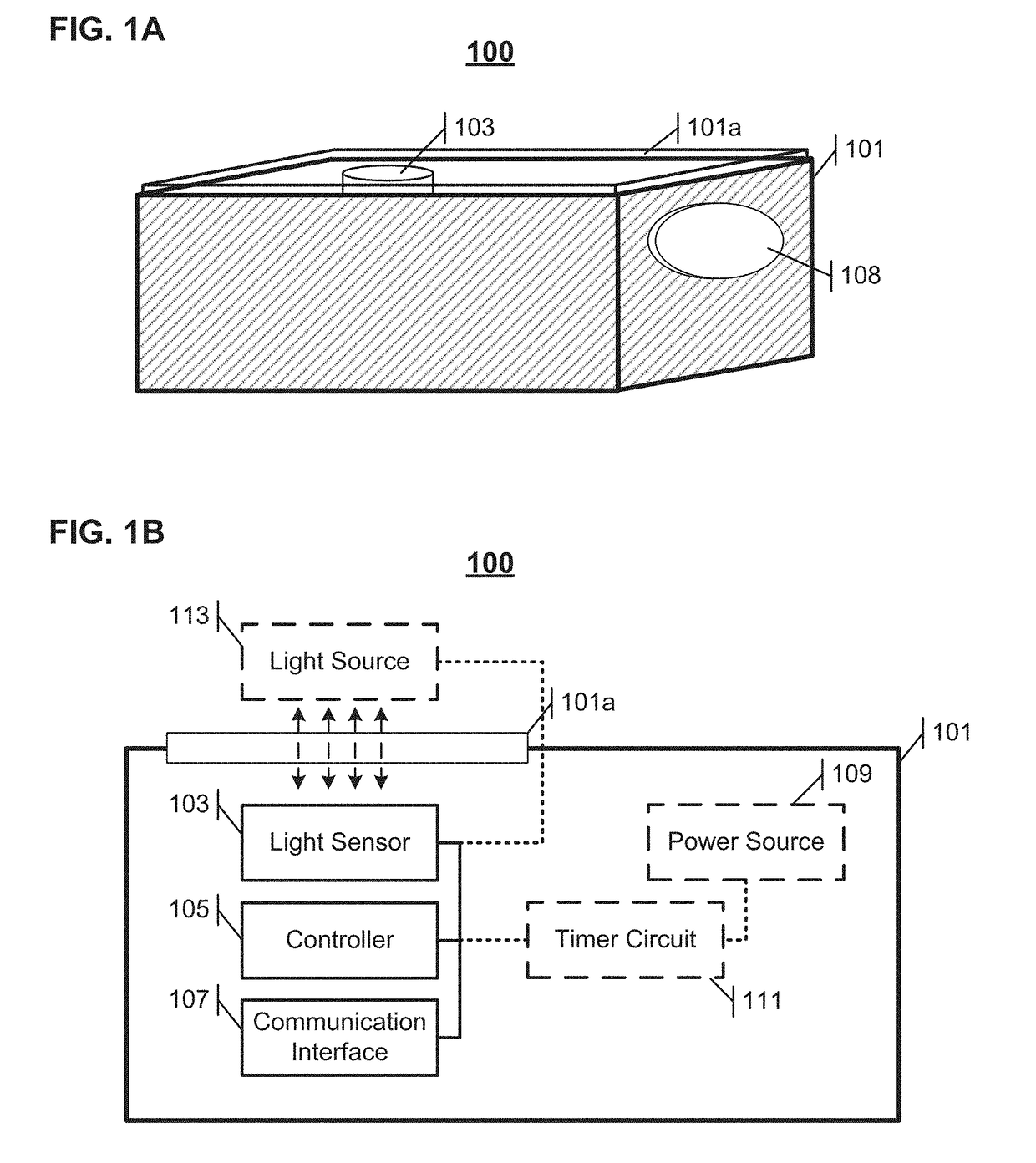
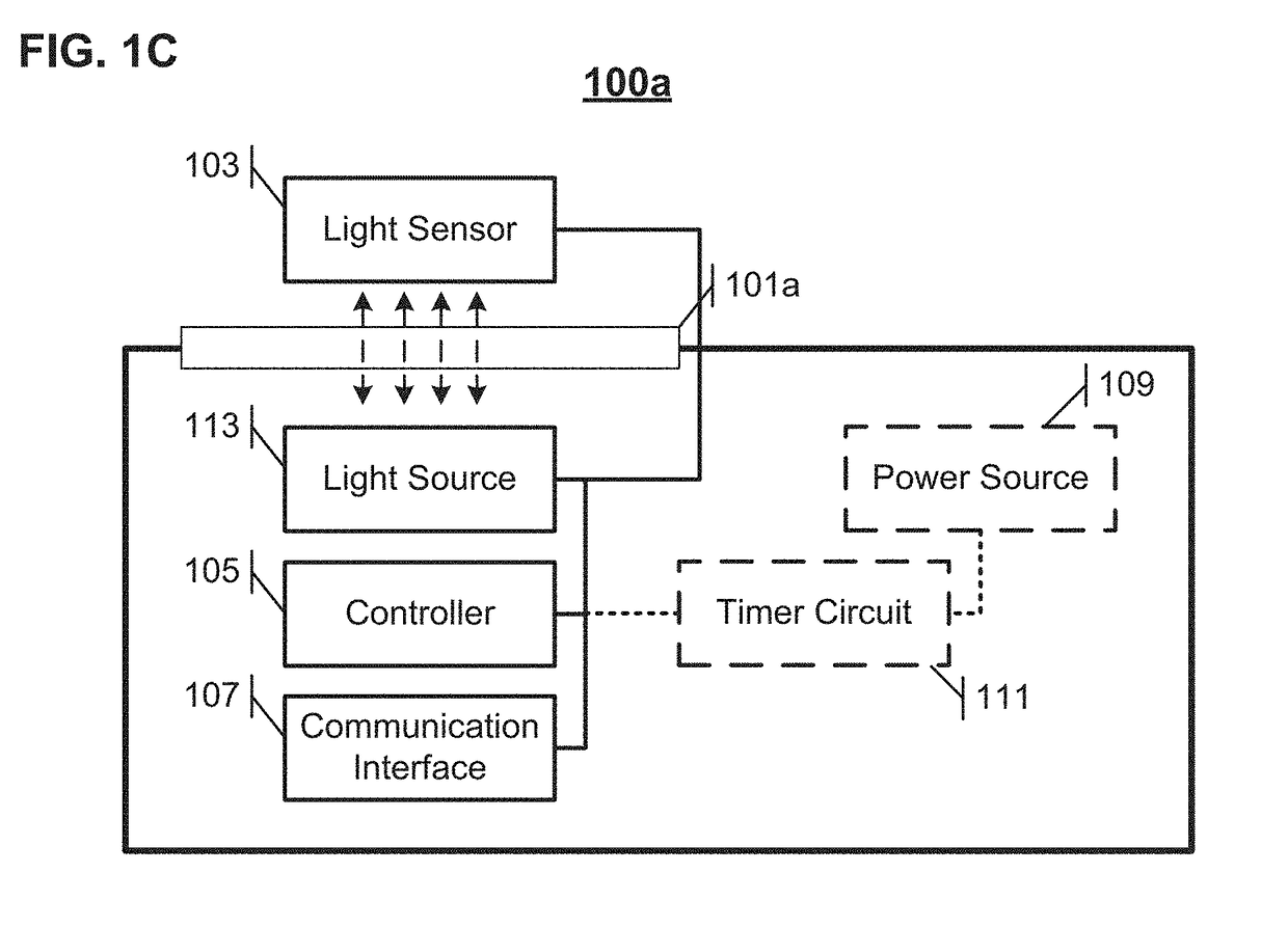
The patent describes a system that can monitor the accumulation of dust. The system includes a casing, a light sensor, a controller, and a communication interface. The casing has a translucent portion, and the light sensor is configured to output a sensing signal that includes light that passes through the translucent portion. The controller is coupled to the light sensor and includes an output interface that outputs an alert based on the sensing signal. The system also includes a light source that is controlled by the controller to output light. The light sensor and light source may be placed on either the same side or opposite sides of the translucent portion of the casing. The system also has a power source and a timer circuit to selectively power the controller. The communication interface can be a sound or light emitter or a communication transceiver to alert the user. The system can reduce dust accumulation and can be used in conjunction with a central monitor to activate machinery interlocks or alert systems. The system may also use wireless communication between the monitors and the central monitor.

Problems solved by technology

Accumulations of dust, including flammable and / or combustible dust, can trigger dust explosions and other dangerous conditions.
Secondary dust explosions are the result of dust accumulations within the facility (e.g., outside of equipment) which occur when the dust is disturbed, suspended, and ignited by the primary explosion, resulting in a more dangerous uncontrolled explosion inside the workplace.
Inspections may involve the use of man-lifts, cranes, and a team of devoted personnel resulting in significant cost burden.
In some chosen device locations (e.g., rafters), the ambient light may be very low, thus reducing the range of the sensor's capability.
In other locations, ambient light may be highly variable thereby introducing uncertainty in the relationship between dust accumulation and light sensed by the photocell.

Method used


Image

  • Dust accumulation monitor
  • Dust accumulation monitor
  • Dust accumulation monitor

Examples


Embodiment Construction

[0036]In the following detailed description, numerous specific details are set forth by way of examples in order to provide a thorough understanding of the relevant teachings. However, it should be apparent to those skilled in the art that the present teachings may be practiced without such details. In other instances, well known methods, procedures, components, and / or circuitry have been described at a relatively high-level, without detail, in order to avoid unnecessarily obscuring aspects of the present teachings.

[0037]The various systems and methods described herein relate to the monitoring of dust accumulations. Such systems and methods may be used, for example, in monitoring of accumulations of dust including flammable or combustible particles and triggering of alerts in response to dust accumulations exceeding an adjustable threshold.

[0038]In order to monitor dust accumulations, some embodiments of dust accumulation monitors as described herein utilize a photocell resistors, s...


PUM


Abstract

Dust accumulation monitors are provided to autonomously monitor dust accumulations. The dust accumulation monitors include a casing having a translucent portion, a light sensor configured to output a sensing signal based on sensed light penetrating through the translucent portion, a controller coupled to the light sensor to receive the sensing signal and configured to output a dust alert signal based on the received sensing signal, and a communication interface coupled to the controller and configured to output an alert based on the dust alert signal output by the controller. A dust accumulation monitoring system includes a plurality of dust accumulation monitors, and a central monitor communicatively connected to each of the plurality of dust accumulation monitors and configured to receive dust sensing signals from each of the plurality of dust accumulation monitors. The dust accumulation monitors may communicate through wired or wireless links with the central monitor.

Description

CROSS-REFERENCE TO RELATED APPLICATION[0001]This application claims the benefit of U.S. Provisional Application No. 62 / 554,357, filed Sep. 5, 2017, the disclosure of which is incorporated by reference herein in its entirety.TECHNICAL FIELD[0002]The present subject matter relates to techniques and equipment to monitor dust accumulation.BACKGROUND[0003]Accumulations of dust, including flammable and / or combustible dust, can trigger dust explosions and other dangerous conditions. Accumulations of flammable dust commonly occur in process plants and other industrial environments, and monitoring of dust accumulations for prompt cleaning is therefore needed to maintain a safe work environment and prevent damage to facilities and machinery.[0004]Dust explosions may be classified as being either primary or secondary in nature. Primary dust explosions typically occur within individual pieces of equipment inside process plants or similar enclosures (baghouse, cyclone, grinder, etc.), and are ge...

Claims


Application Information

Patent Timeline
IPC IPC(8): G01N21/59G08B21/18
CPCG01N21/59G08B21/18G01N21/94
Inventor PARSONS, PHILIP JAMESSTOVER, BENJAMINHOU, YUJIE
Owner BAKER ENG & RISK CONSULTANTS
Learn More