
Electrophoretic medium

a technology of electrophoretic medium and medium, applied in non-linear optics, instruments, optics, etc., can solve the problems of preventing their widespread use, inadequate service life of these displays, and the number of desirable criteria for such fluids, so as to increase the bistability of the medium

Active Publication Date: 2019-02-28
E INK CORPORATION
View PDF3 Cites 0 Cited by
  • Summary
  • Abstract
  • Description
  • Claims
  • Application Information

AI Technical Summary

Benefits of technology

The present invention provides electrophoretic media that can contain various additives such as a charge control agent to control the charge on particles. The media may also contain a polymer to increase its bistability.

Problems solved by technology

Nevertheless, problems with the long-term image quality of these displays have prevented their widespread usage.
For example, particles that make up electrophoretic displays tend to settle, resulting in inadequate service-life for these displays.
The chief difficulty lies in the number of desirable criteria for such a fluid and the difficulty of satisfying all of the criteria at the same time.
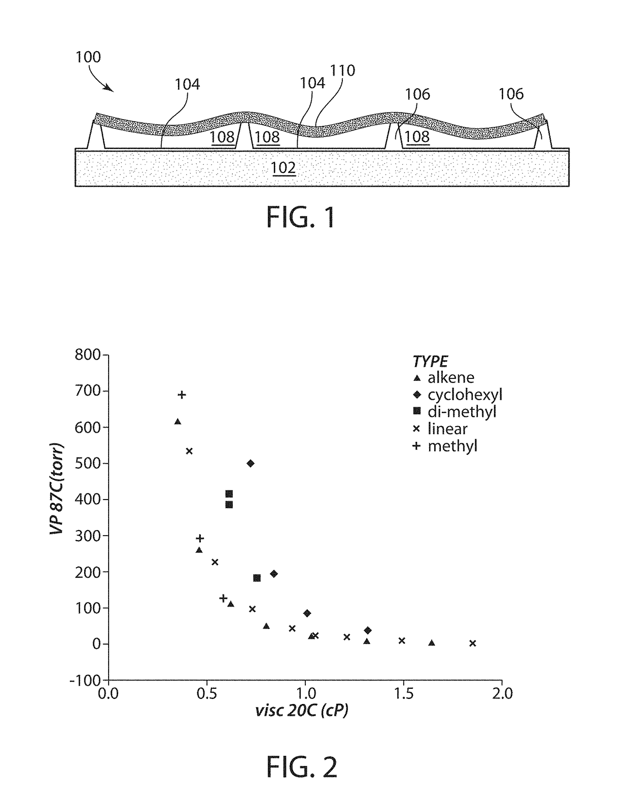
Excessive sag in can lead to broken or cracked sealing layer, the consequent loss of fluid from the affected cells and hindered or non-existent switching.
Moderate sag in can lead to surface roughness of the sealing layer, with associated optical problems due to light scattering, and may also cause problems with void creation during lamination processes, such as those typically used to attach the sealing layer to a backplane or other electrode structure.
The aforementioned problems regarding choice of fluids for use in electrophoretic media have frequently been acknowledged in the literature but are far from solved.
In many cases, the prior art recites lengthy lists of possible fluids with no guidance as to the optimum fluid and without provided any exemplification of the properties of the fluids, apparently leaving the reader to optimize the fluid for each new electrophoretic medium.
These materials would not be appropriate for use in electrophoretic displays because of their relatively high viscosity (˜20 centistokes at 40° C.).
The patent gives no guidance as to how to select an optimal solvent from this rather lengthy list.
Such non-polar solvents may be used alone or in combination.” Again, no guidance is provided on how to select an optimal fluid from this long list.
However, use of halogenated fluids tends to require use of halogenated auxiliary materials, such as charge control agents, and restricts the types of electrophoretic particles which can be used, which is a particular problem in full color displays.
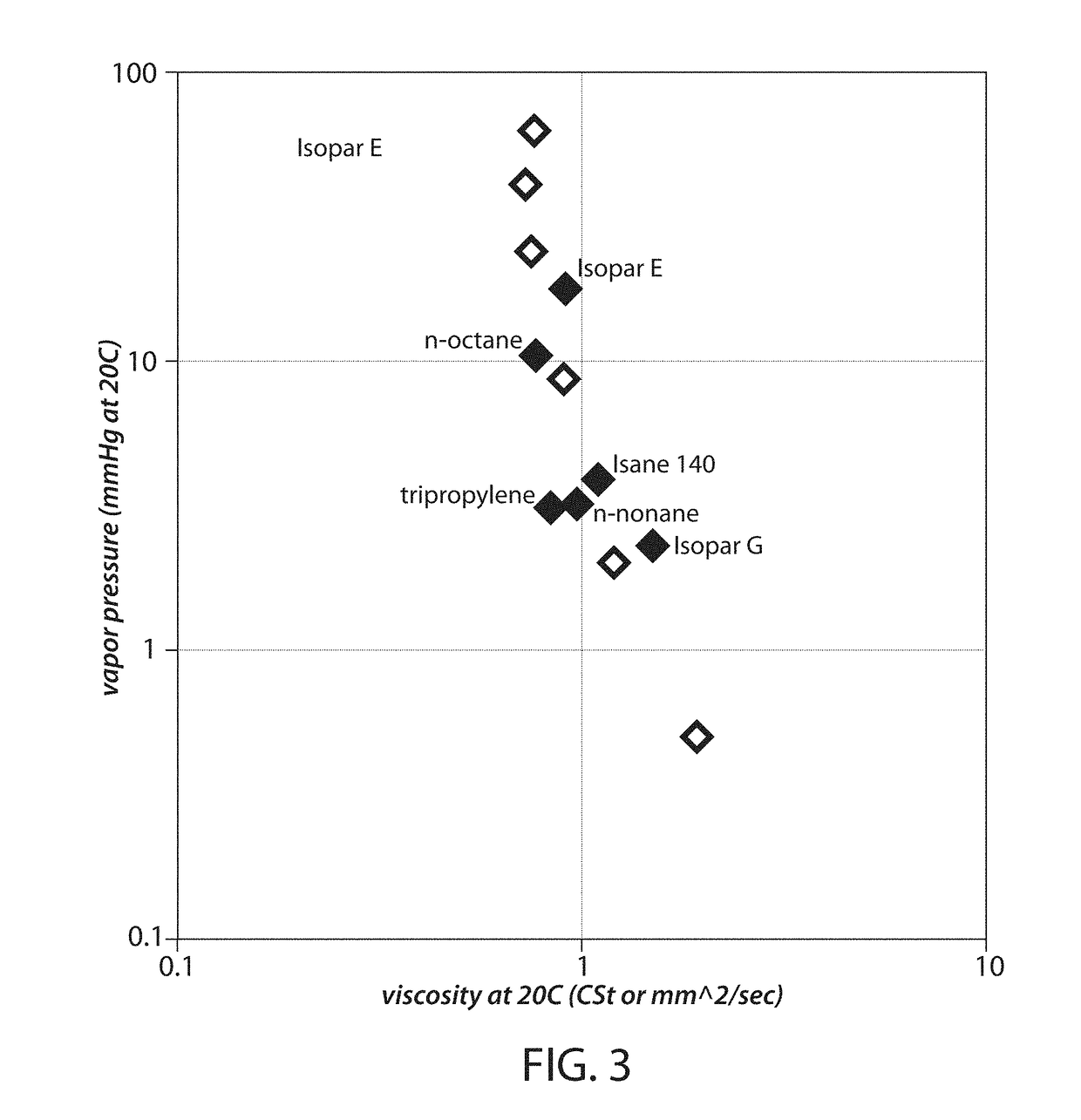
Empirically, it has been found that, although Isopar E gives good results in encapsulated electrophoretic displays, it gives poor results in microcell displays due to high fluid loss and sag in.
Isopar G, which has a lower vapor pressure than Isopar E, results in less fluid loss and lower sag in, but the higher viscosity of Isopar G results in slower switching speeds.

Method used


Image

  • Electrophoretic medium
  • Electrophoretic medium

Examples


Embodiment Construction

[0049]As indicated above, the present invention provides an electrophoretic medium comprising a plurality of charged particles disposed in a fluid, wherein the fluid comprises at least about 75 percent by weight of a hydrocarbon selected from the group comprising monounsaturated nonenes, nonane and methyloctane. It has been found that this relatively narrow class of hydrocarbon fluids provide a nearly ideal combination of low conductivity, low viscosity, and low vapor pressure. These fluids were chosen to give unexpected improvements to both vapor pressure and viscosity over electrophoretic fluids described in the prior art, and are particularly good choices for fluids in microcell media produced by a fill and seal process.

[0050]As already indicated, fluids for use in microcell electrophoretic displays need to possess low conductivity, low viscosity, and low vapor pressure. Low conductivity can be ensured using a hydrocarbon fluid. However, because vapor pressure and viscosity are i...


PUM

PropertyMeasurementUnit
weightaaaaaaaaaa
polarityaaaaaaaaaa
electric fieldaaaaaaaaaa

Abstract

An electrophoretic medium comprises a plurality of charged particles disposed in a fluid. The fluid comprises at least about 75, and preferably at least about 95, percent by weight of a hydrocarbon selected from monounsaturated nonenes, nonane and methyloctane. The electrophoretic medium is especially useful in microcell electrophoretic media comprising a substrate having a plurality of cavities, and a sealing layer closing the open ends of the cavities, the cavities being filled with the electrophoretic medium

Description

REFERENCE TO RELATED APPLICATIONS[0001]This application claims benefit of copending Application Ser. No. 62 / 551,959, filed Aug. 30, 2017.BACKGROUND OF INVENTION[0002]This invention relates to an electrophoretic medium. More specifically, this invention relates to an electrophoretic medium comprising a specific type of fluid, and to microcell and other electrophoretic displays comprising such an electrophoretic medium.[0003]The terms “bistable” and “bistability” are used herein in their conventional meaning in the art to refer to displays comprising display elements having first and second display states differing in at least one optical property, and such that after any given element has been driven, by means of an addressing pulse of finite duration, to assume either its first or second display state, after the addressing pulse has terminated, that state will persist for at least several times, for example at least four times, the minimum duration of the addressing pulse required t...

Claims


Application Information

Patent Timeline
Patent Type & Authority Applications(United States)
IPC IPC(8): G02F1/167
CPCG02F1/167G02F1/1681G02F2001/1678G02F1/16757
Inventor MILLER, DAVID DARRELL
Owner E INK CORPORATION
Learn More