Eureka AIR delivers breakthrough ideas for toughest innovation challenges, trusted by R&D personnel around the world.

Method and Apparatus for Hardware-Configured Network

a hardware-configured network and network technology, applied in electrical equipment, optical transmission, wavelength-division multiplex systems, etc., can solve the problems of significant challenges in the fiber-optic telecommunications industry

Active Publication Date: 2019-02-14
II VI DELAWARE INC
View PDF0 Cites 13 Cited by
  • Summary
  • Abstract
  • Description
  • Claims
  • Application Information

AI Technical Summary

Benefits of technology

The patent text describes the challenges of meeting the growing demand for high capacity data transmissions through optical fibers in a cost-effective and flexible way. This demand requires more efficient and dynamic networks that can reconfigure quickly to changing conditions. The challenge is to create automation and control schemes that can operate across a variety of optical element types, such as transceivers, amplifiers, wavelength filters, wavelength multiplexers, and wavelength demultiplexers. The invention aims to reduce the burden on network operations personnel, allowing larger-scale optical networks to be constructed and operated at lower cost while also improving network flexibility and bandwidth utilization.

Problems solved by technology

The increasing need for high capacity data transmissions through optical fibers, together with the increasing number of optical network elements that are being flexibly and dynamically networked together, presents significant challenges to the fiber-optic telecommunications industry.

Method used


Image

  • Method and Apparatus for Hardware-Configured Network
  • Method and Apparatus for Hardware-Configured Network
  • Method and Apparatus for Hardware-Configured Network

Examples


Embodiment Construction

[0072]Reference in the specification to “one embodiment” or “an embodiment” means that a particular feature, structure, or characteristic described in connection with the embodiment is included in at least one embodiment of the teaching. The appearances of the phrase “in one embodiment” in various places in the specification are not necessarily all referring to the same embodiment.

[0073]It should be understood that the individual steps of the method of the present teachings may be performed in any order and / or simultaneously as long as the teaching remains operable. Furthermore, it should be understood that the apparatus and method of the present teachings can include any number or all of the described embodiments as long as the teaching remains operable.

[0074]The present teaching will now be described in more detail with reference to exemplary embodiments thereof as shown in the accompanying drawings. While the present teachings are described in conjunction with various embodiments...


PUM


Abstract

A method for configuring hardware-configured optical links includes generating a first optical signal comprising a slow scan of wavelength channels where the slow scan has a dwell time on a particular wavelength channel. A second optical signal is generated comprising a fast scan of wavelength channels, where the fast scan has a dwell time on a particular wavelength channel and a complete channel scan time where the slow scan dwell time is greater than or equal to complete channel scan time. The first optical signal is transmitted over a link and a portion is then detected. A pulse of light having a duration that is less than the dwell time on the particular wavelength channel of the fast scan is then detected. Client data traffic is then sent over the link in response to the detected pulse of light and the detected portion of the first optical signal.

Description

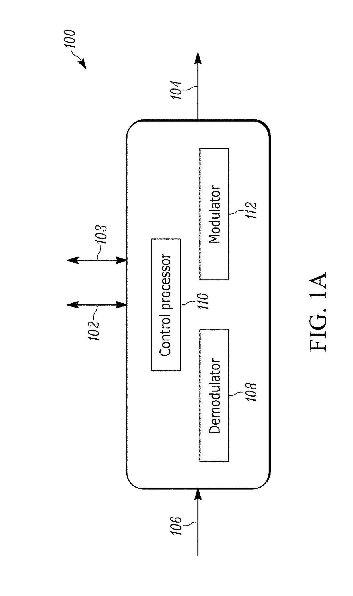
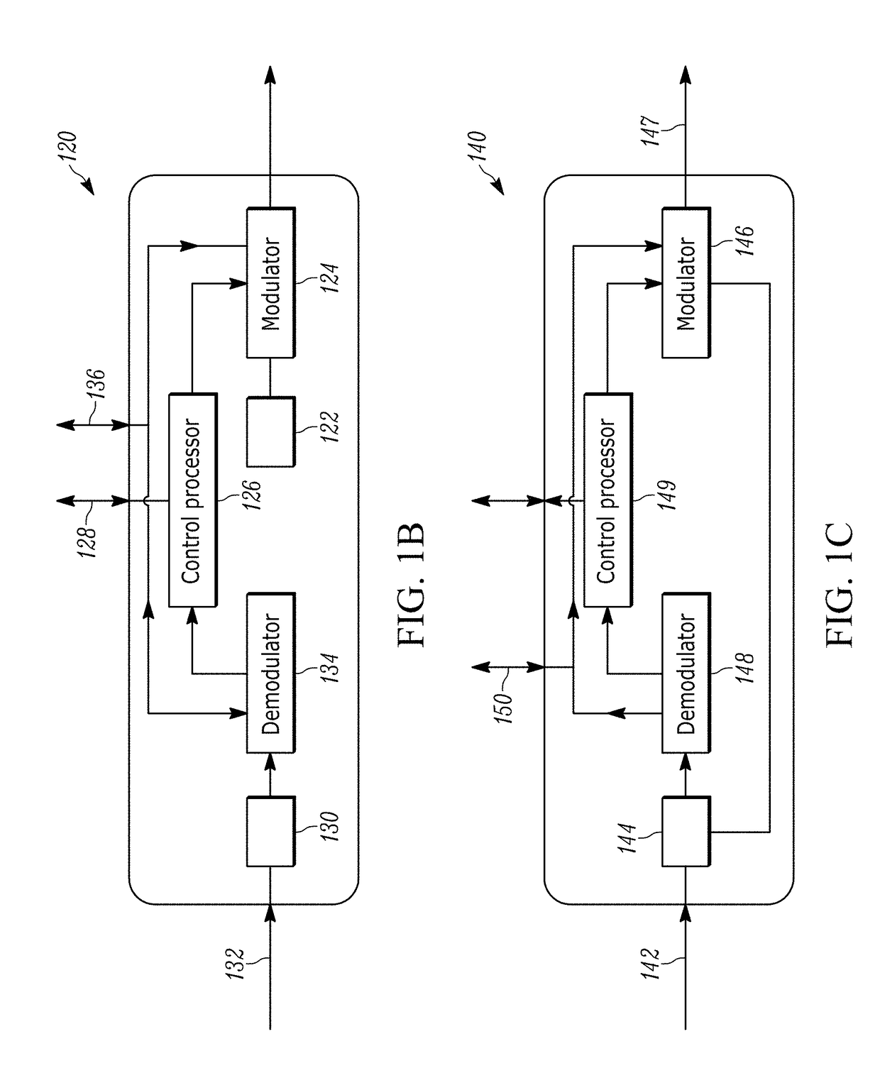
CROSS-REFERENCE TO RELATED APPLICATION[0001]This application is a continuation-in-part of U.S. patent application Ser. No. 15 / 973,829, filed May 8, 2018, entitled “Method and Apparatus for Hardware-Configured Network”, which is a continuation of U.S. patent application Ser. No. 14 / 717,958, filed May 20, 2015, entitled “Method and Apparatus for Hardware-Configured Network”, now issued as U.S. Pat. No. 9,998,254. This application also claims priority to U.S. Provisional Patent Application Ser. No. 62 / 573,142, filed on Oct. 16, 2017, entitled “Method and Apparatus for Hardware-Configured Network”. The entire contents of U.S. Pat. No. 9,998,254, U.S. patent application Ser. No. 15 / 973,829, and U.S. Provisional Patent Application Ser. No. 62 / 573,142 are incorporated herein by reference.INTRODUCTION[0002]The increasing need for high capacity data transmissions through optical fibers, together with the increasing number of optical network elements that are being flexibly and dynamically ne...

Claims


Application Information

Patent Timeline
IPC IPC(8): H04J14/02H04B10/077
CPCH04B2210/074H04J14/0278H04B10/0773H04J14/0212H04J14/0228
Inventor DEANDREA, JOHN
Owner II VI DELAWARE INC
Why Eureka
Eureka Blog
Learn More