
Combiner with a common port and a dually layered cavity

a cavity and common port technology, applied in the field of communication radio frequency cavity devices, can solve the problems of increasing the nonlinear factor of the cavity, increasing the insertion loss, and time and labor consumption, and achieve the effects of convenient manufacturing and assembly, improved application of the mobile communication system, and compact structur

Active Publication Date: 2019-02-07
COMBA TELECOM TECH (GUANGZHOU) CO LTD
View PDF2 Cites 2 Cited by
  • Summary
  • Abstract
  • Description
  • Claims
  • Application Information

AI Technical Summary

Benefits of technology

The present invention provides a combiner that uses a disc for coupling and meets the requirement of port bandwidth of two filter paths of upper and lower cavities. This combiner has the advantage of being more compact and can be better applied for mobile communication system. Compared with prior art, the technical solution of the invention has the advantages of easy assembly, low insertion loss, small size and can meet the required port bandwidth without using an additional common harmonic cavity.

Problems solved by technology

In the first coupling manner it is necessitated that two wires be welded together (one wire is welded to the upper harmonic cavity, while the other wire is welded to the lower harmonic cavity), resulting in time and labor consumption.
In addition, nonlinear factors of the cavity are also increased inevitably due to increase of welding spots.
Using the common harmonic cavity results in addition of another harmonic cavity of the combiner and accordingly, it also results in an increase in insertion loss.
Moreover, a common cavity, which is located in a middle position between the upper cavity and the lower cavity, is utilized, leading to difficulty in manufacture and complicated coupling between the ports and difficult in tuning.

Method used


Image

  • Combiner with a common port and a dually layered cavity
  • Combiner with a common port and a dually layered cavity
  • Combiner with a common port and a dually layered cavity

Examples


Embodiment Construction

[0024]Embodiments of the present invention will be described in detail hereinafter. The examples of these embodiments have been illustrated in the drawings throughout which same or similar reference numerals refer to same or similar elements or elements having same or similar functions. The embodiments described with reference to the drawings are illustrative, merely used for explaining the present invention and should not be regarded as any limitations thereto.

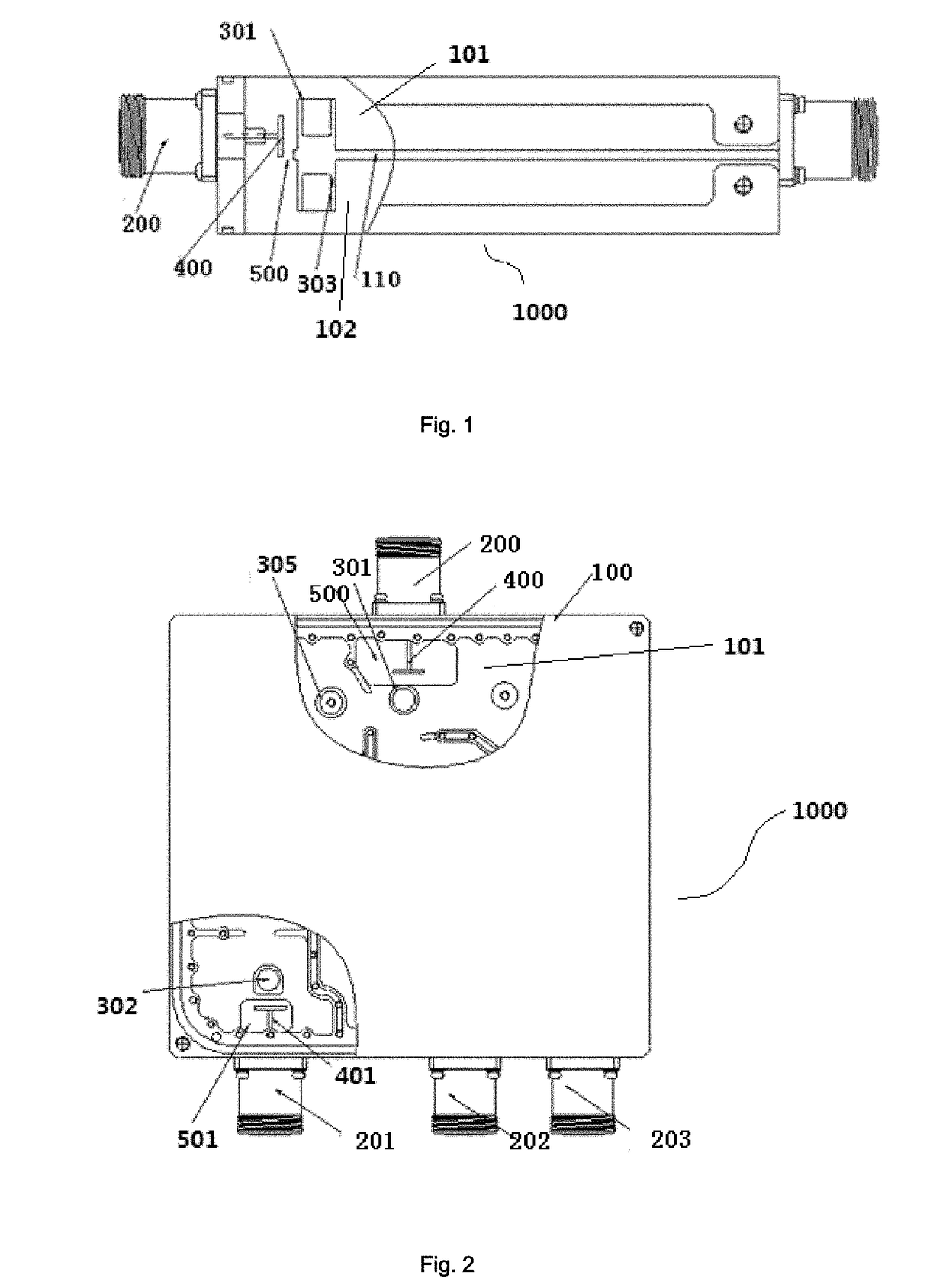
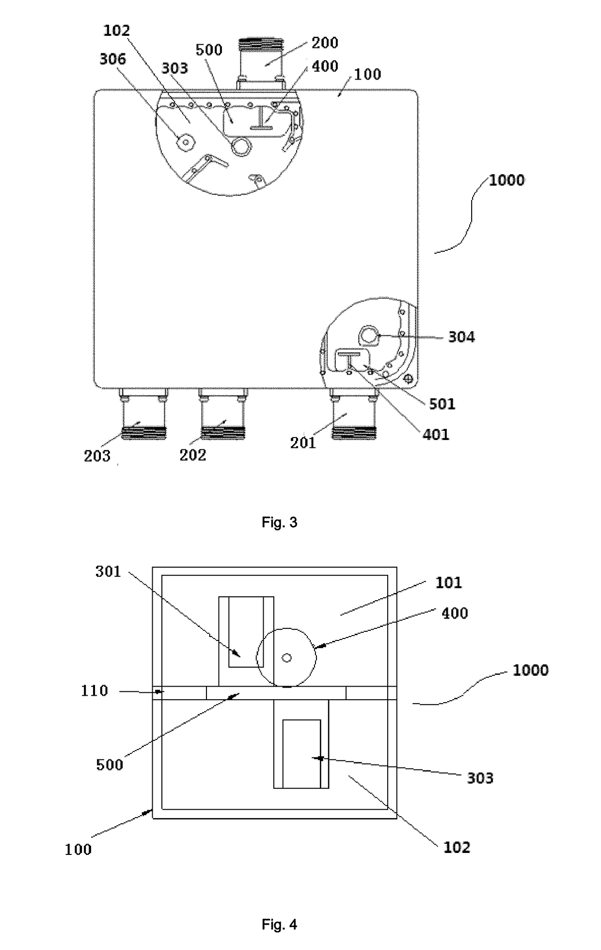
[0025]As showed in FIGS. 1-4, a combiner with a common port and a dually layered cavity 1000 of the invention (hereinafter referred as to “combiner”), incudes a cavity 100, a clapboard 110, a common port (including its joint) 200, a number of for example three signal ports (including their corresponding joints) 201, 202, 203, and a coupling disc.

[0026]The clapboard 110 divides the cavity 100 into an upper cavity 101 and a lower cavity 102, and the same clapboard 110 increases the structural strength of the combiner 1000, and ...


PUM


Abstract

A combiner with a common port and a dually layered cavity includes a cavity, a clapboard used for dividing the cavity into an upper cavity and a lower cavity, a common port, a number of signal posts, and a first coupling disc, said common port and said number of signal ports being disposed at two sides of the cavity respectively. The upper cavity and the lower cavity are each provided with a number of filter paths, and an upper common harmonic post and a lower common harmonic post are disposed at a location close to the common port; a first coupling hole is defined in the clapboard at a location close to the common port, and the first coupling disc is disposed in the first coupling hole and connected with the common port.

Description

FIELD OF THE INVENTION[0001]The present invention generally relates to the field of the communication radio frequency cavity device. More particularly, the present invention relates to a combiner with a common port and a dually layered cavity.BACKGROUND OF THE INVENTION[0002]In current mobile communication techniques, the microwave filter device has already become an indispensable and important component. With the advantage of excellent electromagnetic shielding, compact structure, low pass-band signal loss, small size and high power capacity, the metallic cavity filter has been selected as the first choice of the mobile communication base station transmitting filter for a long time.[0003]For a combiner featuring several pass-bands, the combiner is mostly constructed of a dually layered cavity. The combiner with a dually layered cavity includes a common port in the form of a joint by which an upper filter path and a lower filter path are connected with each other. In a traditional d...

Claims


Application Information

Patent Timeline
Patent Type & Authority Applications(United States)
IPC IPC(8): H01P1/213H01P5/12H01P1/207
CPCH01P1/213H01P5/12H01P1/207H01P1/20H01P1/2138H01P1/2133H01P5/16
Inventor MENG, BIHUIXIE, ZHENXIONGZHOU, GUOMINGWU, JINGQIANGJIN, YUNXIXIA, JINCHAO
Owner COMBA TELECOM TECH (GUANGZHOU) CO LTD
Learn More