
Elastic telescopic module and an elevating device using the same

a technology of elastic telescopic and elevating device, which is applied in the direction of machine supports, mechanical equipment, and stands/trestles, etc., can solve the problems of limiting the range of up and down movement of the display, increasing the risk of constant-force spring breakage, dislocation and deformation, etc., and achieves convenient manufacturing and assembly, short service life, and small size

Active Publication Date: 2022-01-04
JARLLYTEC CO LTD
View PDF10 Cites 0 Cited by
  • Summary
  • Abstract
  • Description
  • Claims
  • Application Information

AI Technical Summary

Benefits of technology

The present invention aims to provide an elastic telescopic module and an elevating device that overcomes the drawbacks of the conventional structure, such as being bulky, unable to meet the requirements of being thinner, and having a short service life. Additionally, the invention provides a solution to the problem of deformation of the stretched constant-force spring and increases the range of movement and flexibility of use. The invention is modulizable, uses smaller size constant-force springs, reduces required space, and prolongs service time.

Problems solved by technology

If the constant-force spring is over-pressed by the lateral plate surface, it would increase the risk that the constant-force spring is broken or dislocated and deformed.
Consequently, larger space is required for the assembly, which further limits the range of the up and down movement of the display.

Method used


Image

  • Elastic telescopic module and an elevating device using the same
  • Elastic telescopic module and an elevating device using the same
  • Elastic telescopic module and an elevating device using the same

Examples


Embodiment Construction

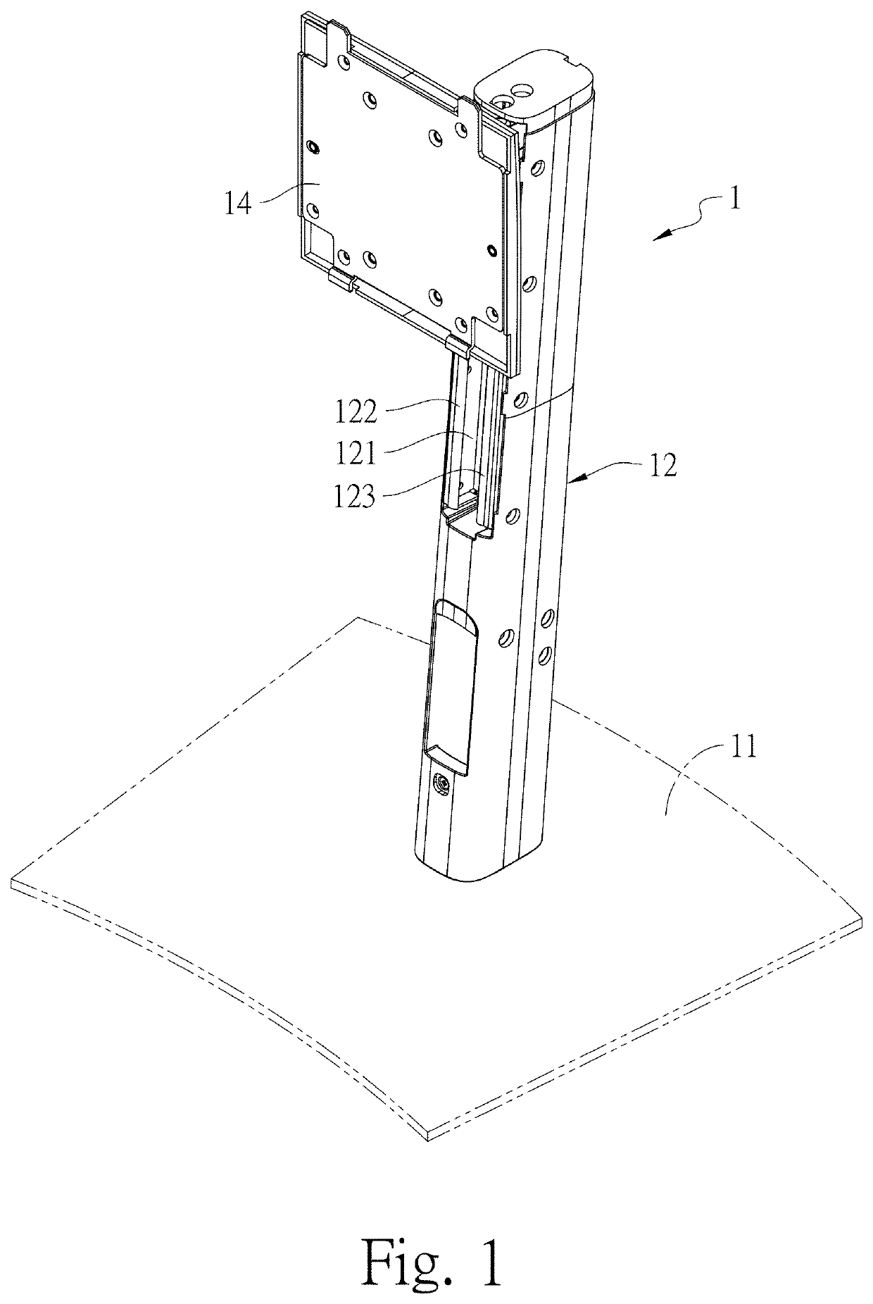
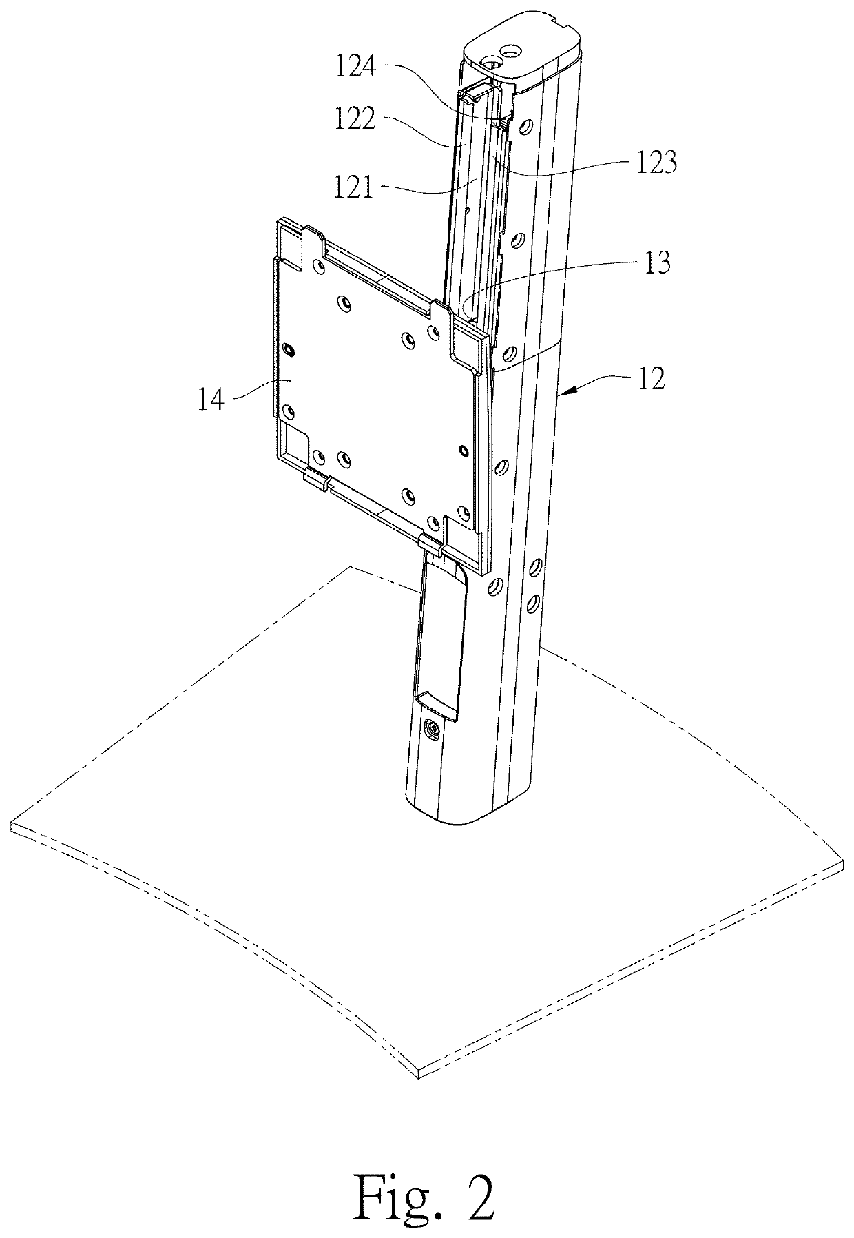
[0036]Refer to FIGS. 1 to 8 showing a preferred embodiment of an elevating structure 1 according to the present invention. The elevating structure 1 comprises a base 11, a support 12, an adapter 13, and an elastic telescopic module 2. The base 11 is placed on a table. The support 12 has a bottom surface connected onto the top surface of the base 11, so that the straight-shaped support 12 stands on the base vertically. The support 12 has one lateral surface recessed with an elongate position-limiting slot 121 for one end portion of the elastic telescopic module (that is, a second frame body 4 and a coil spring part of a second constant-force spring 6) and one opposing end portion (a first frame body 3 and a coil spring part of a first constant-force spring 5) corresponding to above end portion to be connected or disconnected with each other. The opposing end portion of the elastic telescopic module 2 is positioned at the internal wall of the rear side of the elongate position-limitin...


PUM


Abstract

An elevating device comprises a base, a support on the base, an elastic telescopic module on the support, and an adapter connected with the elastic telescopic module. The elastic telescopic module comprises a first frame body with a first accommodating space therein for positioning a first constant-force spring, and a second frame body with a second accommodating space therein for positioning a second constant-force spring. The second frame body has an top end located beneath the first frame body's bottom end, the first constant-force spring has one end passing out of the first accommodating space and fixed onto the bottom end of the second frame body, while the second constant-force spring has one end passing out of the second accommodating space and fixed onto the top end of the first frame body, so that the first and second frame body are moved in a reverse direction.

Description

BACKGROUND OF THE INVENTIONField of Invention[0001]The present invention is related to an elastic telescopic module and an elevating device using the same, and more particularly, to an elastic telescopic module and an elevating device using the same, mounted on the rear side of a display and capable of making the overall structure thinner, prolonging the service time of the display, and increasing the range of upward and downward movement of the display.Prior Art[0002]For conventional displays, it is only able to adjust their elevation angles. Moreover, some conventional displays may be provided with an elevating device to adjust its heights, so as to meet the needs from users with different statures. In general, an elevating device works by means of the relative movement of a fixed sliding track and a movable sliding tract both of which are of constant specifications, so as to move a display up or down, and its resilient force is generated by at least one constant-force spring. Whe...

Claims


Application Information

Patent Timeline
Patent Type & Authority Patents(United States)
IPC IPC(8): F16M11/28
CPCF16M11/28F16M11/24F16M2200/048
Inventor CHENG, CHIEN-WEI
Owner JARLLYTEC CO LTD
Learn More