Wafer Level Integrated Circuit Probe Array and Method of Construction

a probe array and integrated circuit technology, applied in the field of integrated circuit fabrication and testing, can solve the problems that the testing of ic-packed lead will not work without substantial modification, and achieve the effect of easy machine-aware sidewalls

Active Publication Date: 2019-02-07
JOHNSTECH INT
View PDF1 Cites 1 Cited by
  • Summary
  • Abstract
  • Description
  • Claims
  • Application Information

AI Technical Summary

Benefits of technology

[0020]The method can also include cutting away or forming the registration corner or the corner on the pin guide (or both) so that the corners themselves do not touch or meet but that their sidewalls extending away from the corners will precisely engage. This avoids the problem that the corners are slightly mismatched and prevent proper engagement of the sidewalls for alignment since it is easier to machine accurate sidewalls than corners.

Problems solved by technology

The technology used for testing IC leaded packages therefore is not particularly analogous to wafer level testing and we have found principles from IC packed lead testing will not work without substantial modification and inventive input.
Typically such large probe array systems are of limited testing capability for process step called “wafer sort” so simply identify which dies on the wafer can make electrical contact and which dies don't exhibit electrical contact or for burn in.

Method used


Image

  • Wafer Level Integrated Circuit Probe Array and Method of Construction
  • Wafer Level Integrated Circuit Probe Array and Method of Construction
  • Wafer Level Integrated Circuit Probe Array and Method of Construction

Examples


Embodiment Construction

[0137]A typical IC wafer contains between 1k-22k dies typically organized in a regular matrix separated by horizontal and vertical scribe lines, for later cutting into individual dies or chips to be mounted in an IC enclosure with leads or contacts. This disclosure is primarily directed to testing of an individual dies or groups of dies in an array such as a pattern of generally geographically adjacent dies, or multiple arrays simultaneously, before they are cut along the scribe lines, whereafter, each die is inserted into an IC package with leads or contacts.

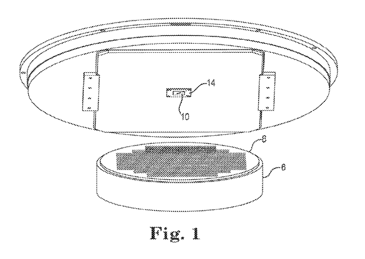
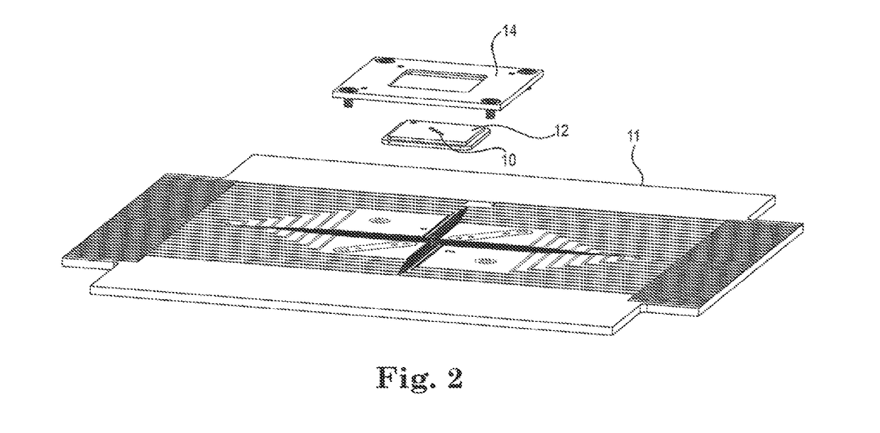
[0138]In the preferred embodiment, as shown in FIGS. 1 and 2, a probe array of contacts 10 is held, preferably close press fit registration to prevent movement, into a pin guide plate / pin guide 12 which itself is affixed onto probe retainer 14 by means of a retainer. Said retainer may include a picture frame opening which has a stepped ledge to accommodate a like ledge on the pin guide plate 12. It is preferable to restrict fre...


PUM


Abstract

A testing device for wafer level testing of IC circuits is disclosed. An upper and lower pin (22, 62) are configured to slide relatively to each other and are held in electrically biased contact by an elastomer (80). To prevent rotation of the pins in the pin guide, a walled recess in the bottom of the pin guide engages flanges on the pins. In another embodiment, the pin guide maintains rotational alignment by being fitted around the pin profile or having projections abutting the pin. The pin guide (12) is maintained in alignment with the retainer 14 by establishing a registration corner (506) and driving the guide into the corner by elastomers in at least one diagonally opposite corner.

Description

CROSS-REFERENCE TO RELATED APPLICATIONS AND INCORPORATION BY REFERENCE[0001]This applications incorporates by reference in its entirety, the following applications: US-2010 / 0231251-A1 (U.S. Ser. No. 12 / 721,039) filed 10 Mar. 2010; U.S. Ser. No. 13 / 343,328 filed 4 Jan. 2012 as a CIP of Ser. No. 13 / 226,606 which claims priority to provisional 61 / 380,494 filed 7 Sep. 2010 and 61 / 383,411 filed 16 Sep. 2010 and US-2012 / 0092034-A1 (U.S. Ser. No. 13 / 276,893) filed 19 Oct. 2011 which itself is a CIP of Ser. No. 12 / 764,603 filed 21 Apr. 2010 which claims 61 / 171,141 filed 21 Apr. 2009, 61 / 257,236 filed 2 Nov. 2009 and 61 / 307,501 filed 24 Feb. 2010, U.S. Ser. No. 13 / 921,484 filed 19 Jun. 2013 and U.S. Ser. No. 61 / 950,404 filed 10 Mar. 2014.BACKGROUNDField of the Disclosure[0002]The present invention concerns integrated circuit fabrication and testing. More particularly, the present invention concerns a methodology and structure for testing multiple integrated circuit dies residing on a semicon...

Claims


Application Information

Patent Timeline
Patent Type & Authority Applications(United States)
IPC IPC(8): G01R1/073G01R1/067G01R3/00
CPCG01R3/00G01R1/07371G01R1/07314G01R1/06738G01R1/06733G01R1/06772G01R1/0466
Inventor EDWARDS, JATHANMARKS, CHARLESHALVORSON, BRIAN
Owner JOHNSTECH INT
Why Eureka
Try Eureka