
Photodetector selection apparatus and method and scattering coefficient measurement apparatus and method

a selection apparatus and selection method technology, applied in the field of scattering coefficient measurement apparatus and method, can solve problems such as difficulty in measuring accurate scattering coefficients

Active Publication Date: 2019-01-31
SAMSUNG ELECTRONICS CO LTD +1
View PDF0 Cites 0 Cited by
  • Summary
  • Abstract
  • Description
  • Claims
  • Application Information

AI Technical Summary

Benefits of technology

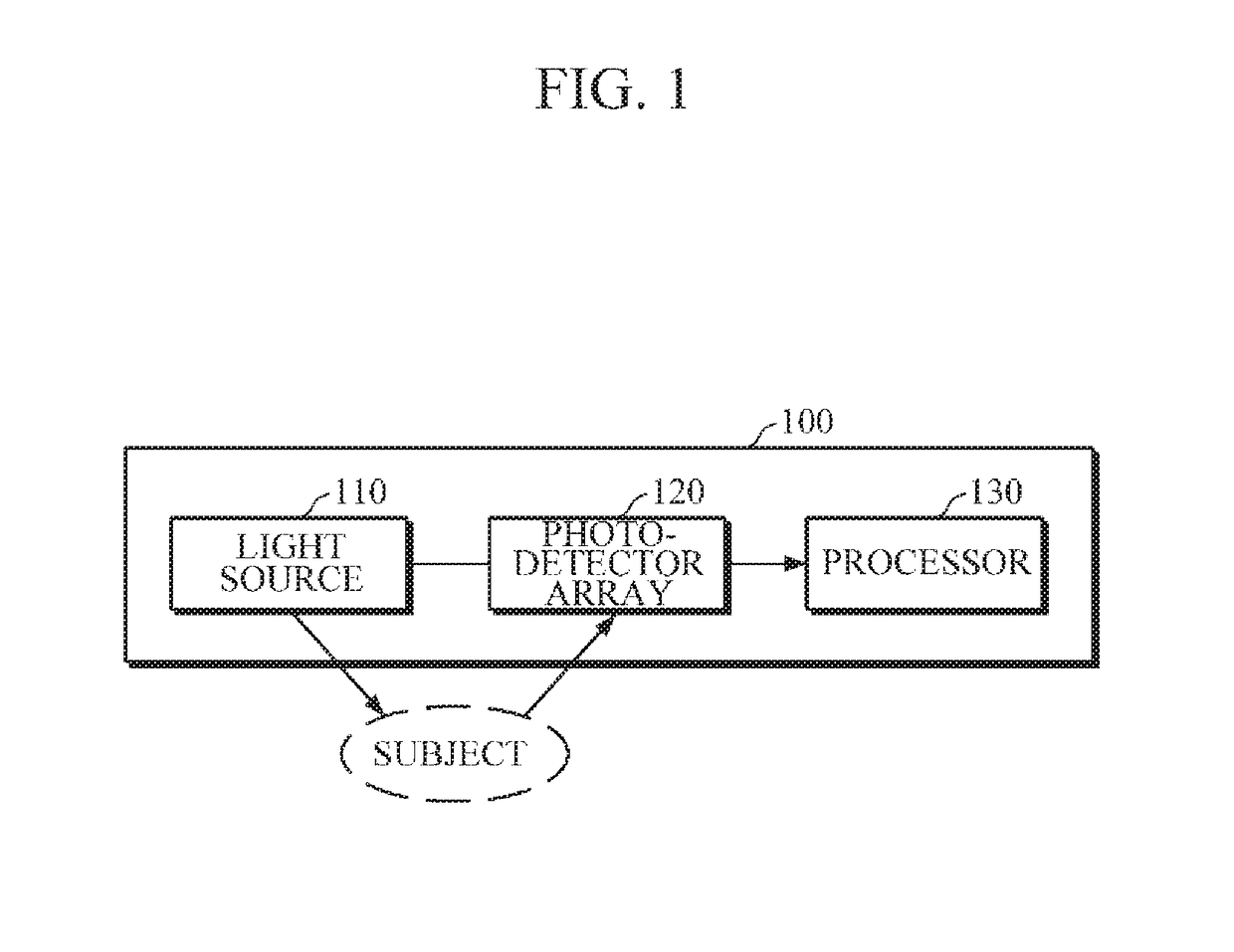
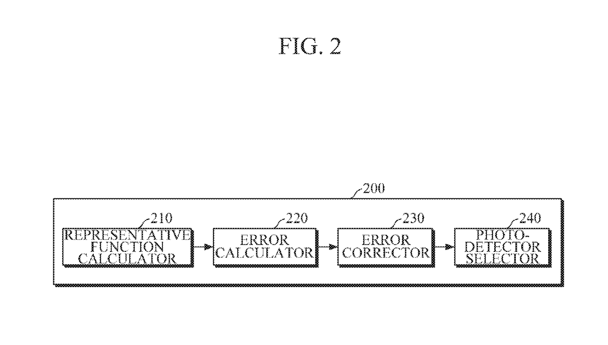
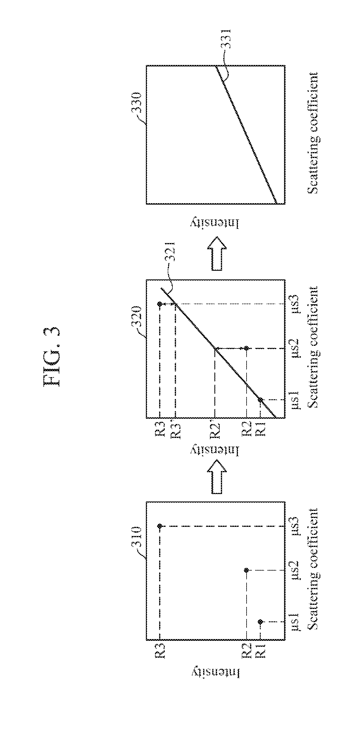
The patent text describes a photodetector selection apparatus and method for measuring a scattering coefficient of a subject. The apparatus includes a light source, a photodetector array, and a processor. The processor selects at least one photodetector from the array based on changes in the light intensity measured by each photodetector as the subject's scattering coefficient changes. The apparatus can correct the measured light intensity using a regression analysis and select the photodetector based on the corrected measurement. The method can also include dividing the array into photodetector sets based on their distance from the light source and selecting the photodetector sets based on their average slope. The technical effects of the patent text include improved accuracy in measuring the scattering coefficient of a subject and more efficient use of the photodetector array.

Problems solved by technology

However, until now, there is no definite criterion for selecting the photodetector at the optimal position, and it is difficult to measure an accurate scattering coefficient.
Also, the exemplary embodiments are not required to overcome the disadvantages described above, and may not overcome any of the problems described above.
The photodetector-specific measurement error for the photodetector-specific representative function may be an extent that a measured light intensity of each specific photodetector deviates from a linearity of a representative function of the specific photodetector.

Method used


Image

  • Photodetector selection apparatus and method and scattering coefficient measurement apparatus and method
  • Photodetector selection apparatus and method and scattering coefficient measurement apparatus and method
  • Photodetector selection apparatus and method and scattering coefficient measurement apparatus and method

Examples


Embodiment Construction

[0046]Exemplary embodiments are described in greater detail below with reference to the accompanying drawings.

[0047]In the following description, like drawing reference numerals are used for like elements, even in different drawings. The matters defined in the description, such as detailed construction and elements, are provided to assist in a comprehensive understanding of the exemplary embodiments. However, it is apparent that the exemplary embodiments can be practiced without those specifically defined matters. Also, well-known functions or constructions are not described in detail since they would obscure the description with unnecessary detail.

[0048]Respective operations described herein may be performed in a different order than that which is explicitly described. In other words, the respective steps may be performed in the same order as described, simultaneously, or in a reverse order.

[0049]Unless the context clearly indicates otherwise, the singular forms include the plural ...


PUM

PropertyMeasurementUnit
scattering coefficientaaaaaaaaaa
light intensityaaaaaaaaaa
distanceaaaaaaaaaa

Abstract

A photodetector selection apparatus and method and a scattering coefficient measurement apparatus and method are provided. The photodetector selection apparatus for measuring a scattering coefficient may include: a light source configured to emit light to a subject; a photodetector array configured to detect the light that is reflected or scattered from the subject and measure a light intensity of the detected light; and a processor configured to select at least one photodetector from a plurality of photodetectors of the photodetector array, based on a change in the measured light intensity of each of the plurality of photodetectors according to a change in a scattering coefficient of the subject, and determine the scattering coefficient of the subject based on the light intensity that is measured by the selected at least one photodetector.

Description

CROSS-REFERENCE TO RELATED APPLICATION(S)[0001]This application claims priority from Korean Patent Application No. 10-2017-0095558, filed on Jul. 27, 2017 in the Korean Intellectual Property Office, the disclosure of which is incorporated herein by reference in its entirety.BACKGROUND1. Field[0002]Apparatuses and methods consistent with exemplary embodiments relate to a scattering coefficient measurement technology.2. Description of Related Art[0003]A scattering coefficient may indicate a ratio of an amount of scattered light to the total amount of input light, and it is widely used in various fields since the constituent material of a subject can be analyzed by using the scattering coefficient.[0004]With regard to a medium (e.g., human body) having a high degree of turbidity, it may be important to select a photodetector at an optimal position in order to increase a sensitivity to the change in scattering coefficient. However, until now, there is no definite criterion for selecting...

Claims


Application Information

Patent Timeline
Patent Type & Authority Applications(United States)
IPC IPC(8): G01N21/49H01L25/16H04B5/00
CPCG01N21/49H01L25/167H04B5/0031G01N21/4738G01N21/94A61B5/14546A61B5/1455G01J1/02G01J1/10G01D1/16G06F17/10G01J2001/444H04B5/72
Inventor LEE, JOON HYUNGKIM, BEOP MINNAM, JUNG YONGCHANG, KI YOUNGPHILLIPS, V, ZEPHANIAHPAIK, SEUNG HO
Owner SAMSUNG ELECTRONICS CO LTD
Learn More