
Lighting device

a technology of light emitting diodes and lighting devices, which is applied in the direction of lighting and heating apparatus, semiconductor devices for light sources, lighting apparatus, etc., can solve the problem that the overall light effect of the bulb cannot meet expectations

Active Publication Date: 2019-01-31
LEEDARSON GREEN LIGHTING
View PDF1 Cites 5 Cited by
  • Summary
  • Abstract
  • Description
  • Claims
  • Application Information

AI Technical Summary

Benefits of technology

The present invention is a lighting device with a bulb shell, base portion, light bar module, core stem, lamp cap, and driving piece. The invention includes inert gases, such as nitrogen or argon, that prevent metal parts from oxidation and increase heat transfer efficiency of the light bar module. The light bar module has multiple light bars, each containing LED chips placed at different angles to achieve a desired lighting angle. By adjusting the main lighting direction of the light bars, the focus of the LED chips can be reduced on the bulb shell, resulting in a more even and complete lighting effect.

Problems solved by technology

For example, if the bulb shell is non-transparent, such as matte, the dark area may make the overall light effect of the bulb fail to meet expectations.

Method used


Image

  • Lighting device
  • Lighting device
  • Lighting device

Examples


Embodiment Construction

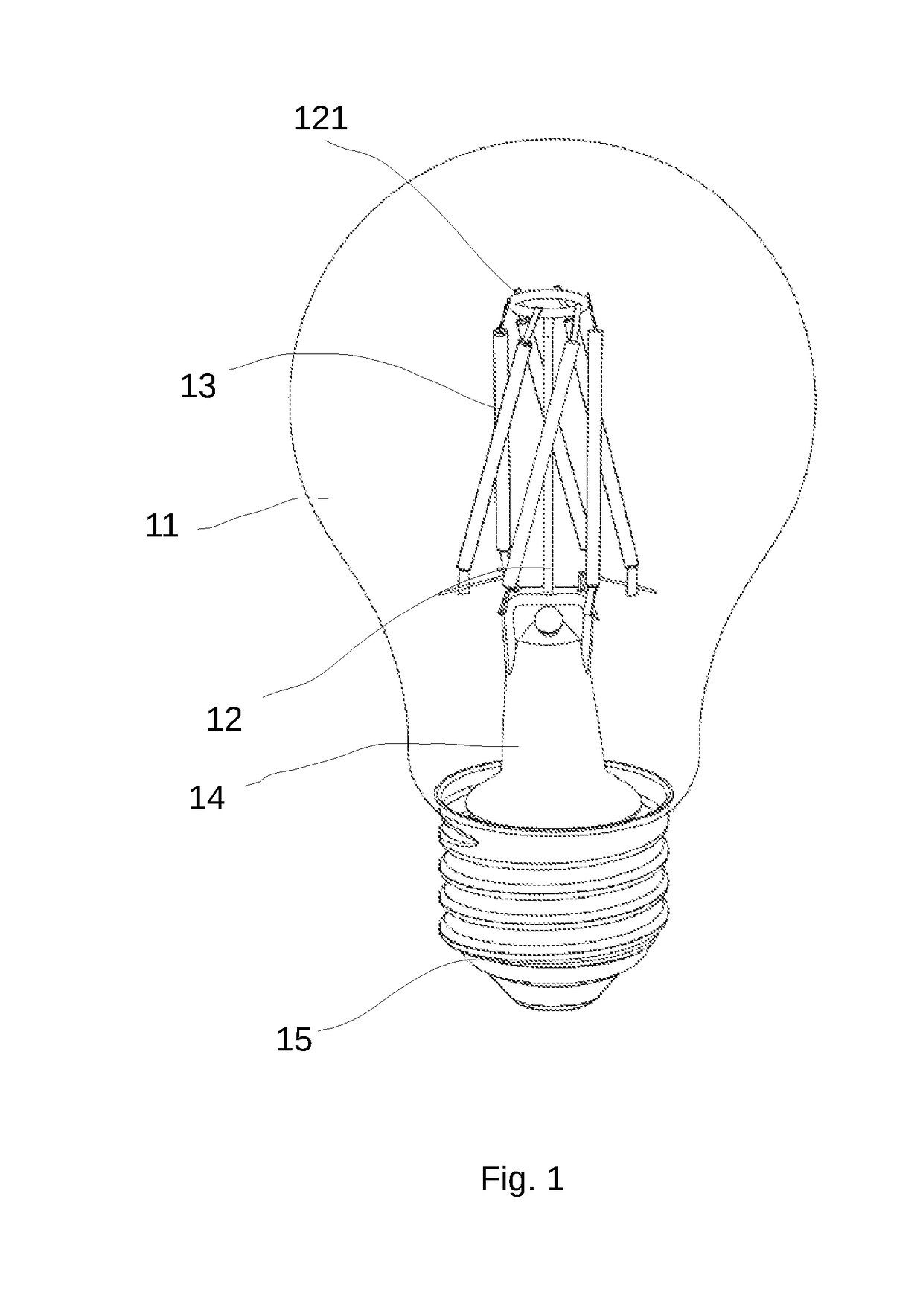
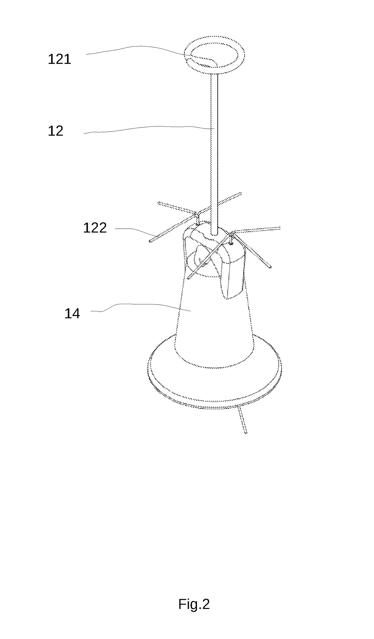
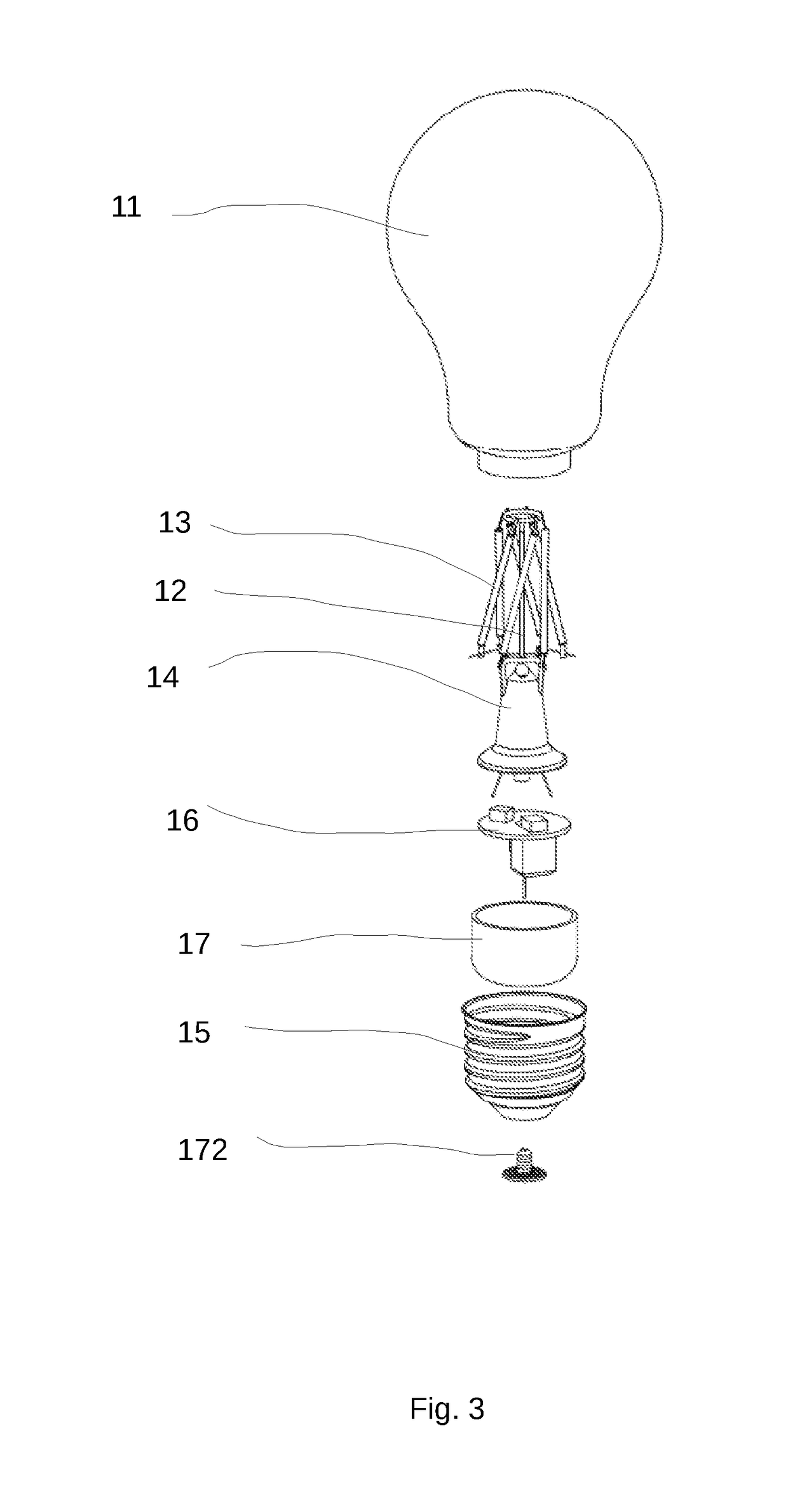
[0052]Please refer to FIG. 1 to FIG. 3. FIG. 1 to FIG. 3 illustrate an example of a lighting device according to present invention. FIG. 1 illustrates an example of a lighting device. FIG. 2 illustrates an enlarged view of partial elements of FIG. 1. FIG. 3 illustrates an exploded view of a lighting device.

[0053]The lighting device includes a bulb shell 11, a base portion 14, a light bar module 13, a core stem 12, a lamp cap 15 and a driving piece 16. The base portion 14 is connected to the bottom of the bulb shell 11 to form a containing space. The base portion 14 has a closed air inlet. The lighting device further includes inert gases. The inert gases are filled in the containing space through the air inlet and maintained within the containing space after the air inlet is closed. On one hand the inert gases can prevent the metal parts in the containing space from oxidation, on the other hand it can increase the heat transfer efficiency.

[0054]The light bar module 13 is placed in th...


PUM


Abstract

A lighting device includes a bulb shell, a base portion, a light bar module, a core stem, a lamp cap and a driving piece. The light bar module is composed of a plurality of light bars. Each light bar houses a plurality of LED chips. Electrical connectors are set at the two ends of each light bar respectively. The core stem extends upwardly from the base portion and has an expansion portion at the top. The electrical connector of light bars is fixed to the expansion portion. The open end of the lamp cap is connected to the bottom of the bulb shell. The driving piece is placed in the lamp cap. The lighting device achieves a technical effect in which the lighting effect is uniform and the lighting angle is large.

Description

FIELD OF THE INVENTION[0001]The present invention is related to a lighting device, and more particularly related to a light emitting diode (LED) lighting device.BACKGROUND OF THE INVENTION[0002]As the development of the LED technology in recent years, the light industry has changed a lot. More and more LEDs have been applied to lighting devices, especially to bulb lights. However, the LED light can't light-round as the incandescent lamp; the light emitted from LEDs has strong directivity. The lighting device with LED light bulbs always light uneven, and it is easy to generate a dark spot at a portion of one end of the bulb due to less light. What's more, because of the strong directivity, the LED bulb lighting device always light with small angle, which can't meet the lighting requirements.[0003]Therefore, how to design a LED lighting device with uniform lighting effect and big lighting angle is the most urgent technical problem to be solved.SUMMARY OF THE INVENTION[0004]The first e...

Claims


Application Information

Patent Timeline
IPC IPC(8): F21K9/232F21V23/00F21V23/06
CPCF21K9/232F21V23/003F21V23/06F21V7/00F21V29/70F21Y2115/10F21K9/238F21V3/00F21V23/006
Inventor CAO, LIANGLIANGCHEN, XIAOBO
Owner LEEDARSON GREEN LIGHTING
Learn More