Vehicle control apparatus

a technology for controlling apparatus and vehicle, which is applied in mechanical apparatus, transportation and packaging, and engine torque, etc., can solve the problems of high risk of generation of considerable engaging shock of the coupling device of the step-variable transmission, and increase in engine torque, so as to reduce the risk of generation of engaging shock of the engaging-side coupling devi

Active Publication Date: 2019-01-31
TOYOTA JIDOSHA KK +1
View PDF0 Cites 5 Cited by
  • Summary
  • Abstract
  • Description
  • Claims
  • Application Information

AI Technical Summary

Benefits of technology

The control apparatus described in this patent is designed to prevent the generation of shocks and noise when shifting gears in a vehicle transmission. The apparatus delays the moment of shifting to allow for a more stable engine output before engaging the gears. This reduces the risk of damage to the transmission and improves the overall control response of the shifting process. The delay in the shifting command can be adjusted based on the estimated time required for the engine to stabilize. The apparatus also restricts the rate of rise of the engine speed to further reduce the risk of shocks.

Problems solved by technology

If a shift-down command to implement the power-on shift-down action is generated immediately after the moment of determination to implement the power-on shift-down action, however, the engine torque (engine power as well) has not been fully raised at a point of time of initiation of an inertia phase of the power-on shift-down action of the step-variable transmission, so that the engine torque and the engine power may increase at a high rate after the initiation of the inertia phase.
Accordingly, there is a risk of generation of a considerable engaging shock of a coupling device of the step-variable transmission in the process of an engaging action of the coupling device, due to a high rate of rise of a rotating speed of an input shaft of the step-variable transmission, namely, a racing of the input shaft, which is caused by surplus torque and power of the engine.
However, a regenerative operation of the electric motor increases a load on a battery, and it is difficult for the electric motor to absorb the surplus torque and power of the engine, when the regenerative operation of the electric motor is limited, so that the engaging shock of the coupling device is undesirably increased in the process of the shift-down action of the step-variable transmission.

Method used


Image

  • Vehicle control apparatus
  • Vehicle control apparatus
  • Vehicle control apparatus

Examples


first embodiment

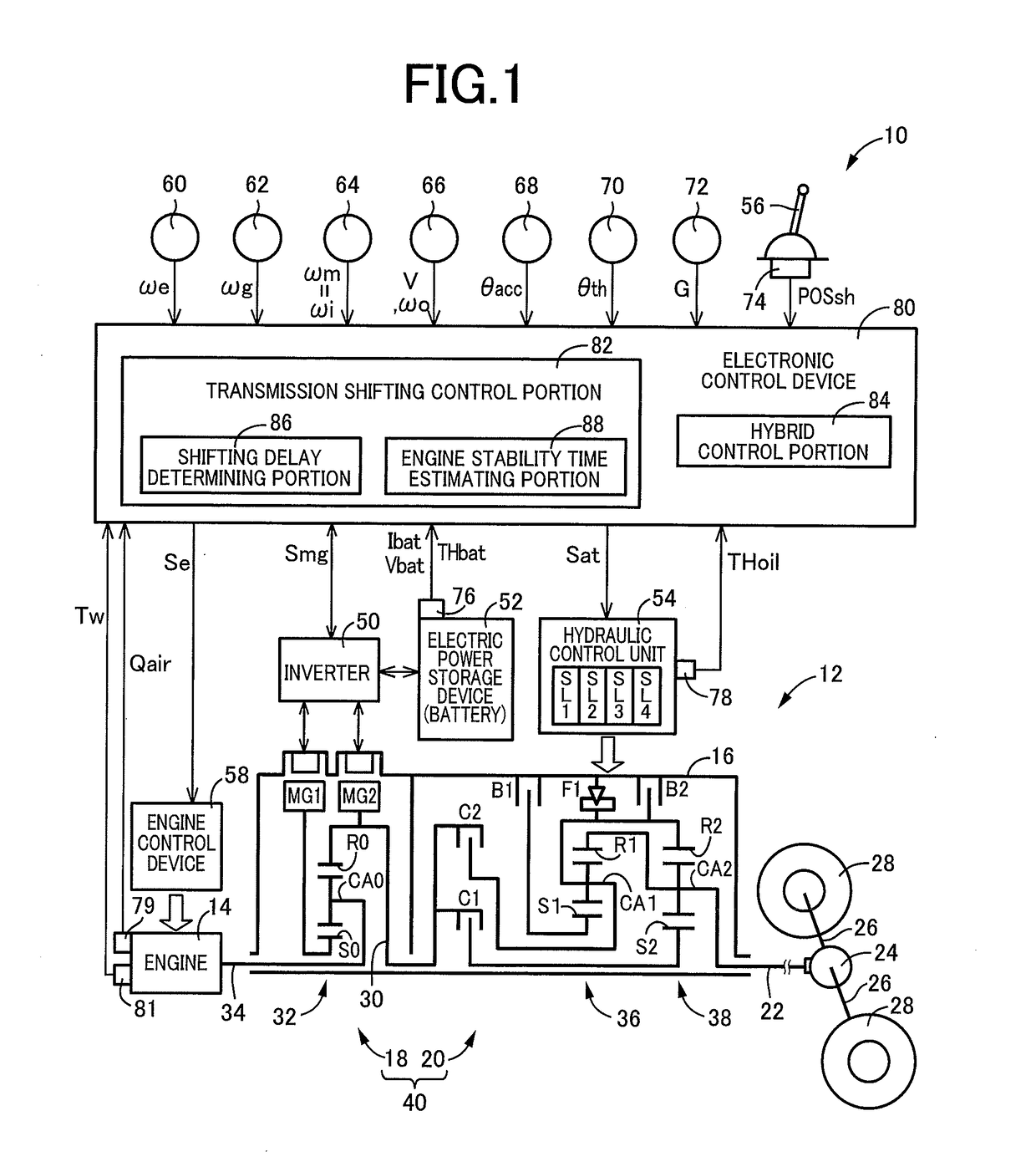
[0037]Reference is first made to FIG. 1, which is the schematic view showing an arrangement of a drive system 12 of a vehicle 10 to be controlled by a control apparatus according to the present invention, and major portions of the control apparatus to perform various controls of the vehicle 10. As shown in FIG. 1, the vehicular drive system 12 is provided with an engine 14 functioning as a drive power source, an electrically controlled continuously variable transmission 18 (hereinafter referred to as “continuously variable transmission 18”) connected directly or indirectly via a damper (not shown) or any other device to the engine 14, and a mechanically operated step-variable transmission 20 (hereinafter referred to as “step-variable transmission 20”) connected to an output rotary member of the continuously variable transmission 18. The continuously variable transmission 18 and the step-variable transmission 20 are disposed in series with each other within a transmission casing 16 (...

second embodiment

[0103]FIG. 9 is the schematic view showing an arrangement of a vehicle 100 to be controlled by a control apparatus according to another embodiment of the present invention, and major control functions and control portions of the control apparatus. This vehicle 100 is provided with an engine 102 functioning as a drive power source, a step-variable transmission 104 having a plurality of coupling devices CB, and a torque converter 106 disposed between the engine 102 and the step-variable transmission 104. The vehicle 100 in this second embodiment is different from the vehicle 10 in the first embodiment in that the vehicle 100 uses only the engine 102 as the drive power source, and is provided with the torque converter 106 between the engine 102 and the step-variable transmission 104. The engine 102 is principally the same as the engine 14 in the first embodiment, and will not be described redundantly. Like the step-variable transmission 20, the step-variable transmission 104 is provide...


PUM


Abstract

A control apparatus for a vehicle provided with a step-variable transmission which is disposed between drive wheels and a drive power source including at least an engine, and which is shifted by changing operating states of coupling devices, the control apparatus including an engine stability time estimating portion configured to estimate a length of stability time required for stabilization of an output state of the engine, when a determination to implement a power-on shift-down action of the step-variable transmission is made, and a control portion configured to delay a moment of generation of a shift-down command to implement the power-on shift-down action of the step-variable transmission, with respect to a moment of the determination to implement the power-on shift-down action, where the estimated length of stability time is longer than a predetermined value.

Description

[0001]This application claims priority from Japanese Patent Application No. 2017-148665 filed on Jul. 31, 2017, the disclosure of which is herein incorporated by reference in its entirety.FIELD OF THE INVENTION[0002]The present invention relates to a control apparatus for a vehicle provided with a mechanically operated step-variable transmission disposed between a drive power source and drive wheels, which control apparatus is configured to reduce an engaging shock of a coupling device of the step-variable transmission in the process of a power-on shift-down action of the step-variable transmission.BACKGROUND OF THE INVENTION[0003]There is well known a vehicle provided with a mechanically operated step-variable transmission disposed between a drive power source and drive wheels. JP-2006-9942A discloses an example of this type of vehicle. This vehicle is a hybrid vehicle the drive power source of which includes an engine, and first and second electric motors which are operatively con...

Claims


Application Information

Patent Timeline
IPC IPC(8): F16H61/02F16H61/686B60W10/115B60W20/00B60K6/445
CPCF16H61/0213F16H61/686B60W10/115B60W20/00B60K6/445F16H59/141B60W2510/0661B60W2510/1095B60W2710/1005B60Y2200/92B60K6/547B60K6/365F16H3/727F16H2200/0043F16H2200/2007F16H2200/2041F16H2200/2066F16H2200/2082F16H37/0826B60W10/06B60W10/08B60W30/19B60W20/15F16H3/66F16H61/0437F16H2003/445F16H2059/147Y02T10/62
Inventor YOSHIKAWA, MASATOKOBAYASHI, NOBUFUSASUYAMA, DAISUKEOKASAKA, KAZUOMIKAYUKAWA, ATSUSHIMAEDA, MITSURU
Owner TOYOTA JIDOSHA KK
Why Eureka
Try Eureka