
Stator for rotary electric machine

a technology of rotary electric machines and stators, which is applied in the manufacture of stators/rotor bodies, magnetic circuit shapes/forms/construction, windings, etc., can solve the problems of complex winding process, difficult winding shaping, and complicated manufacturing process of stators, so as to reduce electrical resistance and increase the welding length of the joining surface

Inactive Publication Date: 2019-01-10
HONDA MOTOR CO LTD
View PDF0 Cites 2 Cited by
  • Summary
  • Abstract
  • Description
  • Claims
  • Application Information

AI Technical Summary

Benefits of technology

The technical effect of this patent is to reduce manufacturing costs of a stator for a rotary electric machine by reducing the number of spots that need to be welded with a laser and preventing damage to the member caused by the laser beam used for welding. This is achieved by blocking the laser beam at the abutted surfaces of the coil segments using a bent surface, which prevents unwanted laser influence on other parts of the stator. Additionally, the welding length is increased by adding projection portions, reducing electrical resistance.

Problems solved by technology

Since such a winding type stator has a configuration in which winding wires are wound while holding insulation paper, a winding process is complicated and the winding shaping is difficult.
For this reason, the manufacturing process of the stator is complicated, and manufacturing costs are increased.
In the coil of the vehicle AC generator disclosed in JP-A-2000-228852, when the abutting surfaces are welded with a laser beam in a state where the end portions of two conductors are abutted against each other, the laser beam passes between the end portions, and thus the insulation coating of another conductor may be damaged, which is not suitable for laser welding.

Method used


Image

  • Stator for rotary electric machine
  • Stator for rotary electric machine
  • Stator for rotary electric machine

Examples


Embodiment Construction

[0042]Hereinafter, embodiments of the invention will be described with reference to accompanying drawings.

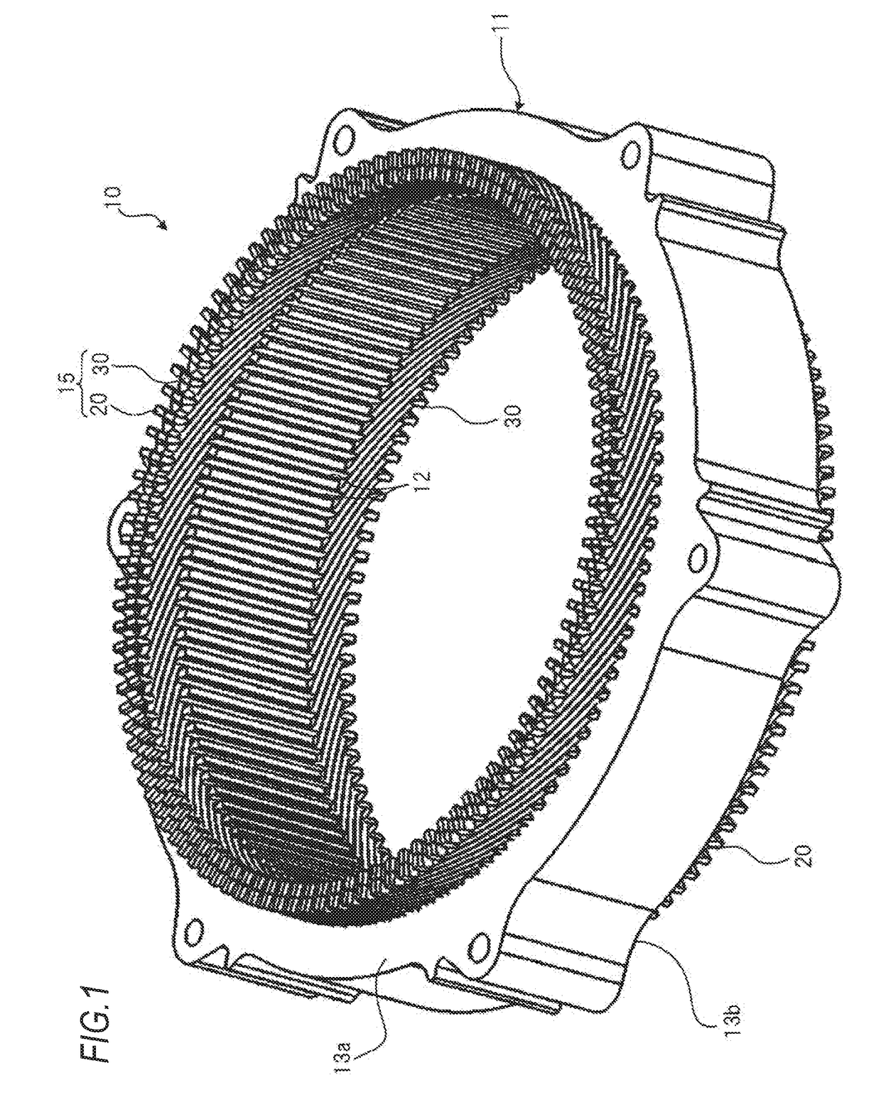
[0043]FIG. 1 is a perspective view of a stator 10 for a rotary electric machine according to an embodiment of the invention.

[0044]As illustrated in FIG. 1, the stator 10 for the rotary electric machine includes a stator core 11 and a coil 15.

[0045]The stator core 11 is, for example, an annular member constituted by laminating a plurality of annular magnetic steel plates. In the stator core 11, a plurality of slots 12 (108 slots in an example of FIG. 1) arranged at regular intervals along a circumferential direction of the stator core 11 is provided on an inner peripheral surface.

[0046]The slot 12 is constituted by a groove extending from one end face 13a in an axial direction of the stator core 11 to the other end face 13b in the axial direction of the stator core 11 (see FIG. 13).

[0047]The coil 15 is inserted into each of a plurality of slots 12 formed in the stator core 11 and...


PUM


Abstract

A stator for a rotary electric machine includes: a stator core; and a coil including a plurality of first coil segments and a plurality of second coil segments; a first coil segment of the plurality of first coil segments includes an insertion portion and a protrusion portion; a second coil segment of the plurality of second coil segments includes an insertion portion and a protrusion portion; the end portion of the protrusion portion of the first coil segment is joined with the end portion of the protrusion portion of the second coil segment; and abutting surfaces, abutting on each other at the protrusion portion of the first coil segment and the protrusion portion of the second coil segment, include: joining surfaces joined to each other; and bent surfaces that are bent in the same direction with respect to the joining surfaces.

Description

CROSS-REFERENCE TO RELATED APPLICATION[0001]The present application claims the benefit of priority of Japanese Patent Application No. 2017-134842, filed on Jul. 10, 2017, the content of which is incorporated herein by reference.BACKGROUND1. Field of the Invention[0002]The present invention relates a stator for a rotary electric machine to be installed in, for example, an electric vehicle or a hybrid vehicle.2. Description of the Related Art[0003]A stator for a rotary electric machine including a stator core and a coil made of winding wires wound around a teeth of the stator core is known.[0004]Since such a winding type stator has a configuration in which winding wires are wound while holding insulation paper, a winding process is complicated and the winding shaping is difficult.[0005]In view of the above, a stator for a rotary electric machine is proposed in WO 2015 / 151200 in which a coil includes a plurality of slot coils inserted into slots of a stator core and a plurality of conn...

Claims


Application Information

Patent Timeline
Patent Type & Authority Applications(United States)
IPC IPC(8): H02K1/16H02K3/48H02K15/02H02K15/04
CPCH02K1/165H02K15/04H02K15/024H02K3/48H02K1/16H02K3/04H02K3/50H02K3/12H02K15/0421
Inventor PYDIN, ANDRII
Owner HONDA MOTOR CO LTD
Learn More