
Shipping container and method of construction thereof

a technology of shipping containers and containers, applied in the field of shipping containers, can solve the problems of many problems still affecting the performance of containers, no longer meeting the loading/stacking/handling requirements, and likely affecting the performance of some current containers, so as to increase the length of the weld interface and therefore the strength. the effect of increasing the strength of the header assembly

Pending Publication Date: 2022-03-10
IPA PATENTS LLC
View PDF3 Cites 0 Cited by
  • Summary
  • Abstract
  • Description
  • Claims
  • Application Information

AI Technical Summary

Benefits of technology

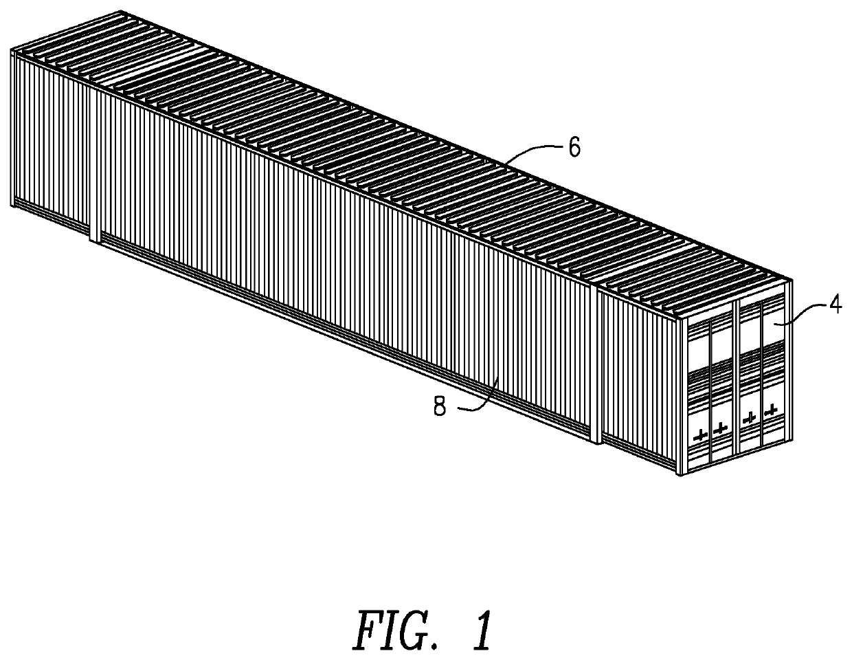
The present invention provides an intermodal shipping container with enhanced design features that increase the cargo volume while reducing the overall weight. This includes the use of intermediate gable posts and rear lower castings that provide greater strength and anticipated longevity. Additionally, the container includes rear header assemblies with internal gussets to further enhance the strength of the container.

Problems solved by technology

In fact, the performance of some current containers may have actually been compromised to achieve some of the (customer requested) design targets to such a point that they very likely no longer meet the required loading / stacking / handling requirements as mandated by AAR M-930 (or similar / equivalent governing industry standards).
However, many problems still exist with containers.

Method used


Image

  • Shipping container and method of construction thereof
  • Shipping container and method of construction thereof
  • Shipping container and method of construction thereof

Examples


Embodiment Construction

[0034]The following terminology can be defined interchangeably: 40′ gable (or just “gable”), intermediate stacking post, and stacking frame; Gable header, gable upper (or top) channel and plate assembly, intermediate header and intermediate frame upper (or top) member; Rear intermediate bolster, rear 40′ gable (or rear intermediate stacking post / frame), lower (or bottom) channel and plate assembly, and lower (or bottom) cross member; Upper casting and upper handling fitting; Lower rear casting, lower 53′ rear casting, and lower rear corner casting. The same terminology is also applicable to all size shipping containers including 60′, for example.

[0035]There are four bolsters in the floor of a container. The front bolster is the lower structural member of the front facing wall which engages with the front bolster of the associated chassis. The two, intermediate bolsters connect the lower, intermediate 40′ castings, respectively and form the lower portions of the structural “ring” of ...


PUM


Abstract

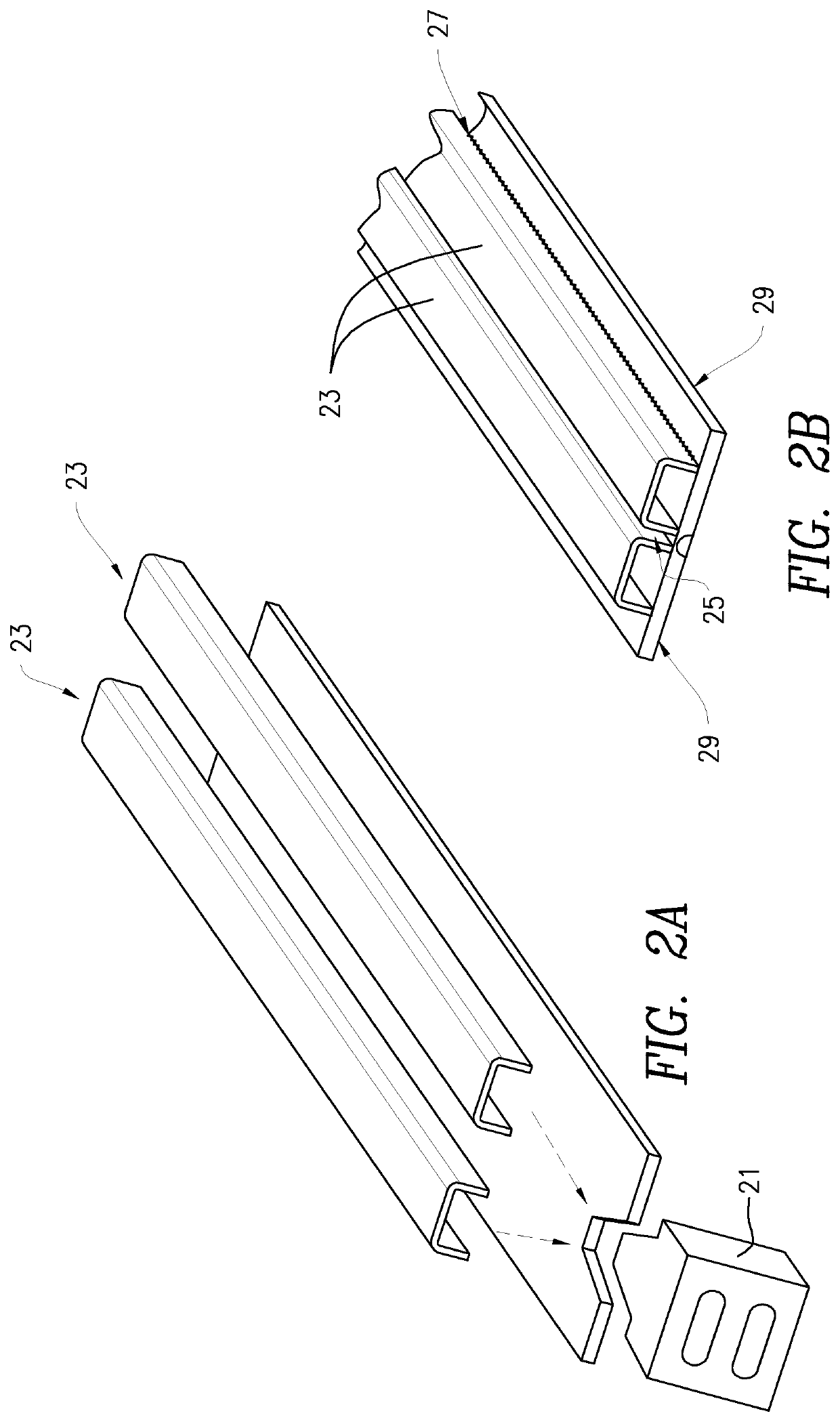
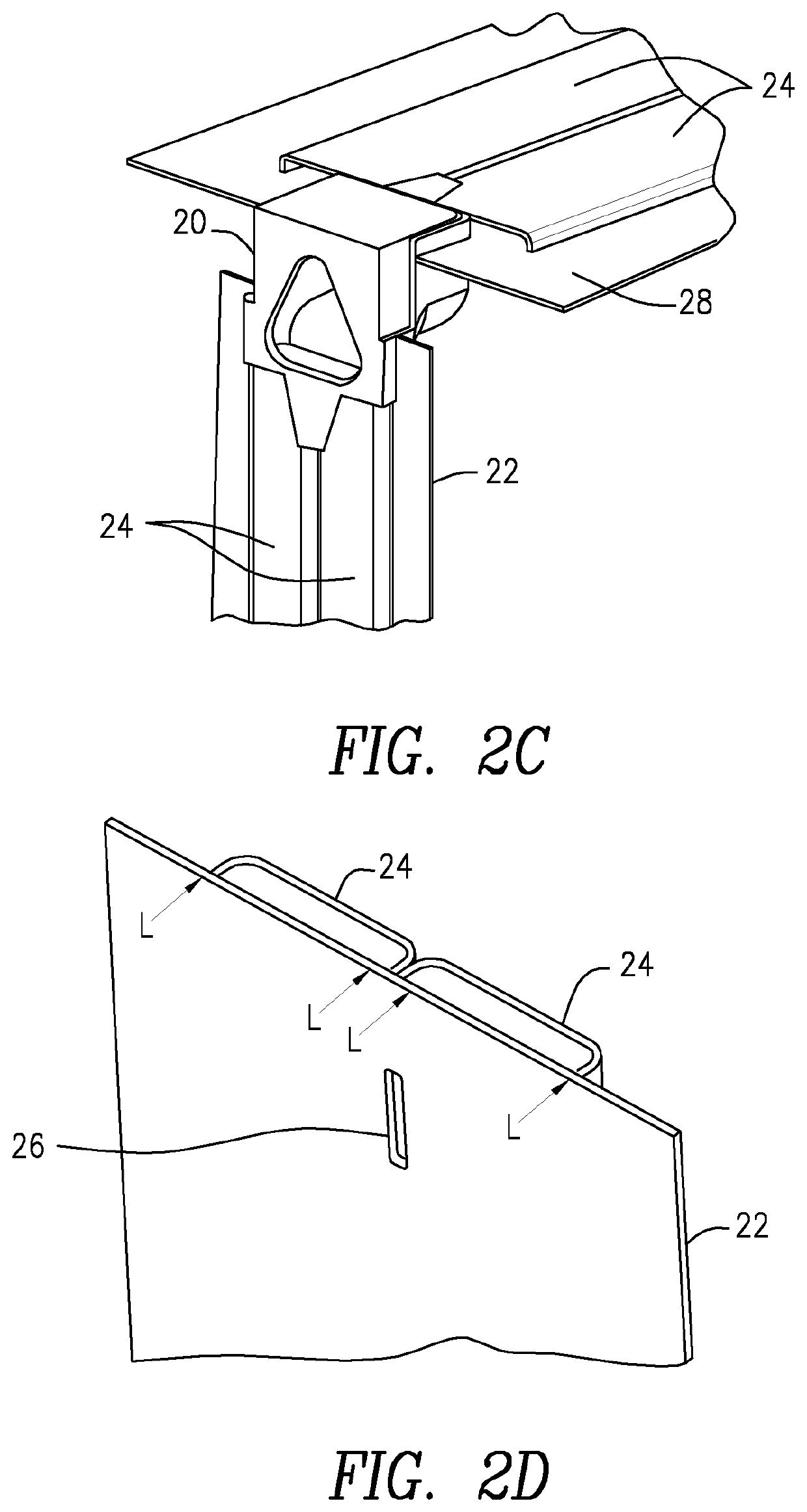
An intermodal shipping container including one or more improvements such as intermediate gable posts or gable headers adapted to increase an internal width and strength of the container, wherein the gable posts or the gable headers include twin channels having at least two internal flanges welded to a gable post plate or gable header plate, one or more upper castings having an integral top rail ledge, wherein a top rail of a side wall hangs on the integral top rail ledge, “C” channel style beam main frame cross members, a one-piece continuous top plate including an integral lip connecting the top plate and a roof, one or more rear lower castings, wherein the one or more rear lower castings are an integral interlocking interface, a bolster including an integral seating and fastening surface and slots, and / or one or more nested rear corner posts subassemblies, the one or more nested rear corner posts having a notch and protrusion connection, wherein a protrusion in a lower rear casting engages with a corresponding notch in the rear corner post.

Description

[0001]This application claims priority to U.S. Provisional Patent Application No. 63 / 076,061 filed Sep. 9, 2020, entitled “SHIPPING CONTAINER AND METHOD OF CONSTRUCTION THEREOF,” which is hereby incorporated by reference herein.[0002]The present invention relates to reusable intermodal shipping containers.BACKGROUND OF THE INVENTION[0003]Containers are used to transport materials. The containers may be transported by trucks on the highway, by trains on the railway and or by nautical vessels, for example. They may be individual or stacked on top of one another.[0004]The basic design of intermodal containers has changed very little over the past 25 years. In fact, the performance of some current containers may have actually been compromised to achieve some of the (customer requested) design targets to such a point that they very likely no longer meet the required loading / stacking / handling requirements as mandated by AAR M-930 (or similar / equivalent governing industry standards).[0005]...

Claims


Application Information

Patent Timeline
Patent Type & Authority Applications(United States)
IPC IPC(8): B65D88/12B65D90/08
CPCB65D88/121B65D90/08B65D90/02B65D90/0026B65D90/008
Inventor TAYLOR, JOHN S.MATTHEWS, BRENT W.MARCU, MIHAIL ION
Owner IPA PATENTS LLC
Learn More