
Soundproof structure and adjustment method of soundproof structure

a sound absorption and structure technology, applied in the direction of synthetic resin layered products, building components, constructions, etc., can solve the problems of difficult selection of sound absorption materials, inconvenient sound absorption of equipment and automobiles, and heat accumulation on the inside, etc., to achieve high sound absorption

Active Publication Date: 2019-01-03
FUJIFILM CORP
View PDF25 Cites 10 Cited by
  • Summary
  • Abstract
  • Description
  • Claims
  • Application Information

AI Technical Summary

Benefits of technology

The present invention provides a soundproof structure that can selectively block sound of a specific frequency and change the cutoff frequency of the sound. This structure is light and thin, with high robustness and air permeability. It is suitable for various applications such as equipment, automobiles, and general households. The adjustment method of the structure allows for easy adjustment of the cutoff frequency of the sound.

Problems solved by technology

However, in the sound absorber, there is a problem that it is difficult to select a sound absorbing material since the range of selection of a sound absorbing material is narrow.
In addition, since the sound absorbing material of such a sound absorber completely blocks the through-hole of the frame body, the sound absorbing material does not allow wind and heat to pass therethrough and accordingly heat tends to accumulate on the inside.
For this reason, there is a problem that such a sound absorber is not suitable for the sound insulation of equipment and automobiles, which is disclosed in JP4832245B.
For this reason, it has been difficult to effectively use the sound absorber disclosed in JP4832245B in general equipment or automobiles in which specific frequency components, such as motor sounds, are often strongly generated in a pulsed manner.
For this reason, in the sound absorber disclosed in JP4832245B, there is a problem that it is necessary to redesign the sound absorber in accordance with the changed frequency and manufacture the sound absorber again.

Method used


Image

  • Soundproof structure and adjustment method of soundproof structure
  • Soundproof structure and adjustment method of soundproof structure
  • Soundproof structure and adjustment method of soundproof structure

Examples


Embodiment Construction

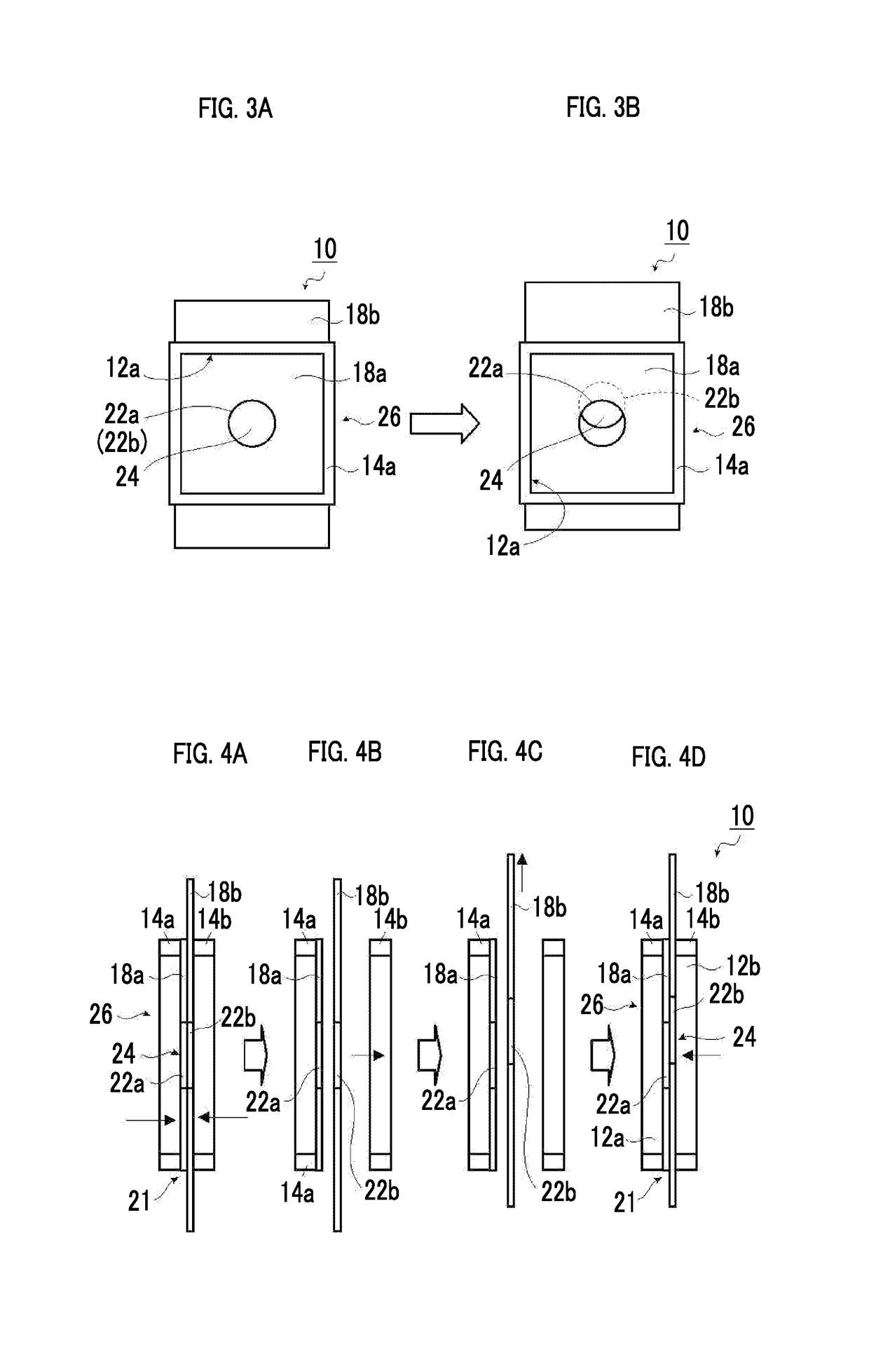
[0060]Hereinafter, a soundproof structure and an adjustment method of a soundproof structure according to the present invention will be described in detail with reference to preferred embodiments shown in the accompanying diagrams.

[0061]Hereinafter, a case where the number of films, such as thin films forming a soundproof structure, is two and the number of holes drilled in one film is one will be described as a representative example. However, the present invention is not limited thereto, and it is needless to say that the number of films may be three or more or the number of holes may be two or more.

[0062]FIG. 1 is a plan view schematically showing an example of a single soundproof cell of a soundproof structure according to an embodiment of the present invention, and FIG. 2 is a schematic cross-sectional view of the soundproof structure shown in FIG. 1.

[0063]A soundproof structure 10 of a first embodiment of the present invention shown in FIGS. 1 and 2 is configured to include on...


PUM

PropertyMeasurementUnit
distancesaaaaaaaaaa
sizesaaaaaaaaaa
sizesaaaaaaaaaa

Abstract

There is provided a soundproof structure that can selectively block sound having a specific frequency emitted from equipment, automobiles, and general households and can change the cutoff frequency of the sound in accordance with a change in the frequency of sound to be blocked. The above problem is solved by providing a laminated film, in which two or more films each including one or more holes drilled therein are laminated, and two rigid frames, which fix the laminated film so as to be interposed from both sides of the laminated film, and making at least parts of the one or more holes in the respective films of the laminated film overlap each other.

Description

CROSS-REFERENCE TO RELATED APPLICATIONS[0001]This application is a Continuation of PCT International Application No. PCT / JP2017 / 005034 filed on Feb. 13, 2017, which claims priority under 35 U.S.C § 119(a) to Japanese Patent Application No. 2016-060271 filed on Mar. 24, 2016. Each of the above application(s) is hereby expressly incorporated by reference, in its entirety, into the present application.BACKGROUND OF THE INVENTION1. Field of the Invention[0002]The present invention relates to a soundproof structure for selectively blocking sound having a specific frequency and an adjustment method of a soundproof structure. Specifically, the present invention relates to a soundproof structure that, in the case of laminating a plurality of different films in which holes having a predetermined size are provided and fixing the films with a rigid frame having a predetermined size, can adjust the frequency of sound to be selectively strongly shielded by changing the relative position relation...

Claims


Application Information

Patent Timeline
Patent Type & Authority Applications(United States)
IPC IPC(8): G10K11/162E04B1/84B32B5/26B32B37/12
CPCG10K11/162E04B1/8409B32B5/26B32B37/1292E04B2001/8433B32B2307/102B32B3/08B32B3/266B32B5/022B32B5/028B32B7/08B32B7/12B32B9/007B32B9/04B32B9/041B32B9/045B32B9/047B32B15/043B32B15/08B32B15/082B32B15/085B32B15/088B32B15/09B32B15/12B32B15/14B32B15/18B32B15/20B32B23/04B32B23/042B32B23/08B32B23/10B32B27/08B32B27/10B32B27/12B32B27/28B32B27/281B32B27/283B32B27/285B32B27/286B32B27/288B32B27/304B32B27/306B32B27/308B32B27/32B32B27/322B32B27/34B32B27/36B32B27/365B32B27/40B32B29/02B32B2260/021B32B2260/046B32B2262/101B32B2262/106B32B2307/202B32B2307/408B32B2307/51B32B2307/54B32B2307/72B32B2307/724B32B2307/732B32B2509/00B32B2605/00B60R13/08E04B1/86E04B1/994E04B2001/8447G10K11/172
Inventor NAYA, MASAYUKIHAKUTA, SHINYAYAMAZOE, SHOGO
Owner FUJIFILM CORP
Learn More