Protective baffles for gas turbine noise attenuation system

Inactive Publication Date: 2018-12-27
GENERAL ELECTRIC CO
View PDF9 Cites 0 Cited by
  • Summary
  • Abstract
  • Description
  • Claims
  • Application Information

AI Technical Summary

Benefits of technology

The present patent provides a method for operating an exhaust system for combustion gases from a gas turbine engine. The method involves receiving the gas flow, redirecting it approximately 90 degrees, and then channeling it into a silencer section with multiple baffles. These baffles have different shapes to help create a more even flow of gas. The gas is then guided off the baffles to achieve a more homogeneous flow. The technical effect of this patent is to improve the performance and efficiency of gas turbine engines by promoting a more uniform gas flow and reducing the pressure drop.

Problems solved by technology

During normal operation of a gas turbine engine, one of the main aerodynamic challenges involves the efficient discharge of the high momentum combustion gas flow exiting the turbine.
Although it may be aerodynamically beneficial to use a horizontal exhaust configuration, such an axial exhaust may be impractical due to the overall footprint implications.
The performance of the silencer section may be impacted by the nature of the combustion gas flow in that a non-homogenous flow may be less effective.
Moreover, the baffles may be subject to damage and / or a reduced lifetime caused by the high velocity flow.
Insufficient noise reduction also may result in increasing the length of the ductwork and hence the overall costs involved in the gas turbine engine.
The exhaust system also may be subject to backflow given the common venting of the combustion gases and the engine room.

Method used


Image

  • Protective baffles for gas turbine noise attenuation system
  • Protective baffles for gas turbine noise attenuation system
  • Protective baffles for gas turbine noise attenuation system

Examples


Embodiment Construction

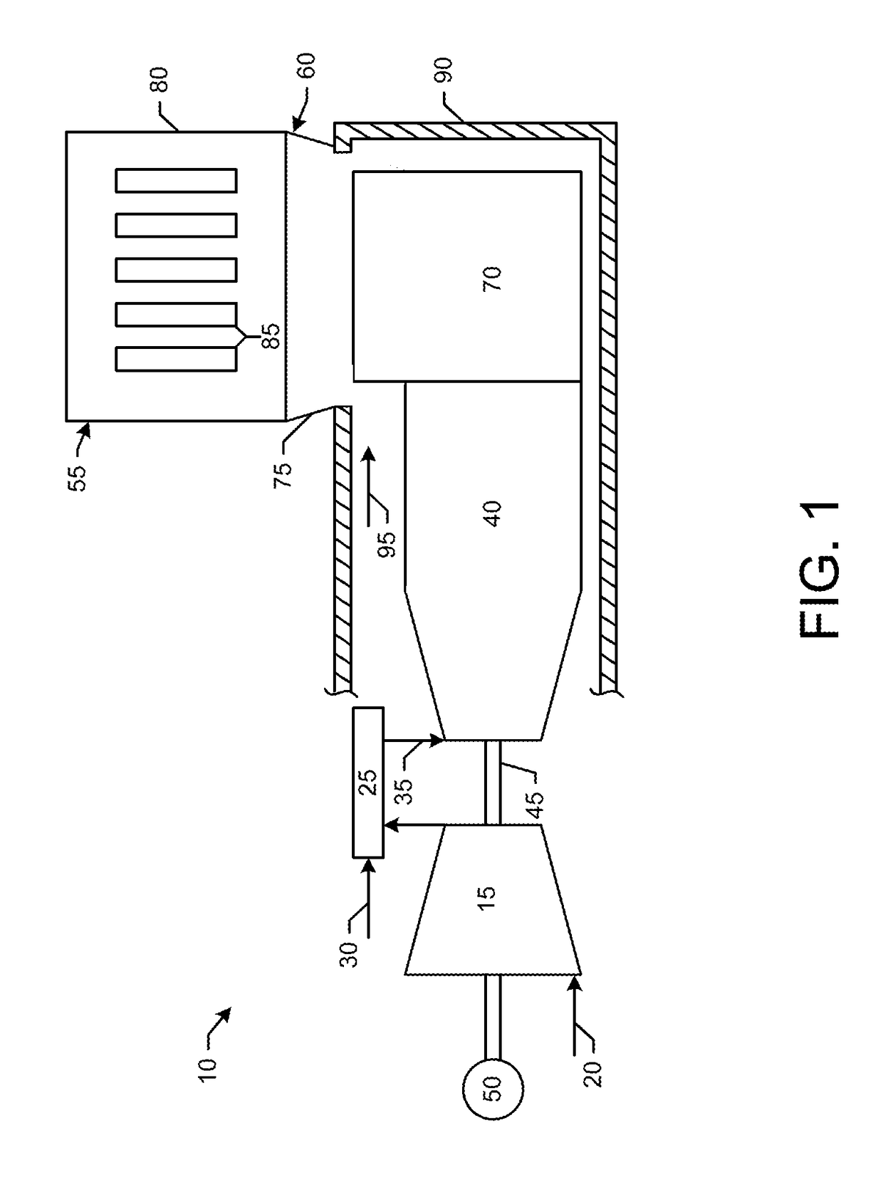
[0012]Referring now to the drawings, in which like numerals refer to like elements throughout the several views, FIG. 1 shows a schematic diagram of gas turbine engine 10 as may be used herein. The gas turbine engine 10 may include a compressor 15. The compressor 15 compresses an incoming flow of air 20. The compressor 15 delivers the compressed flow of air 20 to a combustor 25. The combustor 25 mixes the compressed flow of air 20 with a pressurized flow of fuel 30 and ignites the mixture to create a flow of combustion gases 35. Although only a single combustor 25 is shown, the gas turbine engine 10 may include any number of combustors 25. The flow of combustion gases 35 is in turn delivered to a turbine 40. The flow of combustion gases 35 drives the turbine 40 so as to produce mechanical work. The mechanical work produced in the turbine 40 drives the compressor 15 via a shaft 45 and an external load 50 such as an electrical generator and the like.

[0013]The gas turbine engine 10 may...


PUM


Abstract

The present application provides an exhaust system to exhaust combustion gases from a gas turbine engine. The exhaust system may include an exhaust collector and an exhaust stack with a silencer section. The silencer section may include a number of baffles therein. The baffles may include a number of nose cones facing the combustion gases. The nose cones may include a first shape and a second shape.

Description

TECHNICAL FIELD[0001]The present application and resultant patent relate generally to gas turbine engines and more particularly relate to a gas turbine engine with a compact exhaust system having an exhaust stack, exhaust ducts, and an exhaust noise attenuation system designed to promote a more homogeneous flow therethrough, reduced noise output, and a reduced possibility of backflow.BACKGROUND OF THE INVENTION[0002]During normal operation of a gas turbine engine, one of the main aerodynamic challenges involves the efficient discharge of the high momentum combustion gas flow exiting the turbine. Although it may be aerodynamically beneficial to use a horizontal exhaust configuration, such an axial exhaust may be impractical due to the overall footprint implications. Given such, it is standard practice to use a vertical and side mounted exhaust stack that radially turns the combustion gas flow from an axial turbine. Specifically, the exhaust system ductwork may be used to direct the c...

Claims


Application Information

Patent Timeline
IPC IPC(8): F01D25/30
CPCF01D25/30F05D2260/96F05D2240/126F05D2220/32F01D25/305F01N1/08F02C7/24F05D2250/23F05D2250/21
Inventor POLCWIARTEK, MARCINWASZKIEWICZ, ALEKSANDERNAGORSKI, ARKADIUSZ BARTLOMIEJOLZAK, BARTOSZDREZEK, PRZEMYSLAW SEBASTIANDUDEK, MARIANBABIUCH, MIROSLAW PAWELGAWLOWSKI, SEBASTIAN
Owner GENERAL ELECTRIC CO
Why Eureka
Try Eureka