
Robot arm mechanism

a robot arm and arm mechanism technology, applied in the field of robot arm mechanisms, can solve the problems of increasing workload, not only downtime, but also workload, and achieve the effects of high safety reliability, low working efficiency, and increasing workload

Inactive Publication Date: 2018-12-27
LIFE ROBOTICS CO LTD
View PDF9 Cites 7 Cited by
  • Summary
  • Abstract
  • Description
  • Claims
  • Application Information

AI Technical Summary

Benefits of technology

The purpose of this invention is to create a robot arm mechanism that is highly safe and trustworthy.

Problems solved by technology

However, surrounding the robot with a safety fence might lower working efficiency when the robot works in collaboration with the operator.
Also, in a situation in which the robot is moved and caused to carry out different collaborative tasks, it is necessary to re-install the safety fence each time, increasing not only downtime, but also workloads, which is very troublesome.

Method used


Image

  • Robot arm mechanism
  • Robot arm mechanism
  • Robot arm mechanism

Examples


Embodiment Construction

[0017]A robot arm mechanism according to an embodiment of the present invention is described below with reference to the drawings. The robot arm mechanism according to the present embodiment is described by taking a vertical articulated robot arm mechanism equipped with a linear extension and retraction mechanism as an example, but the robot arm may be of another type.

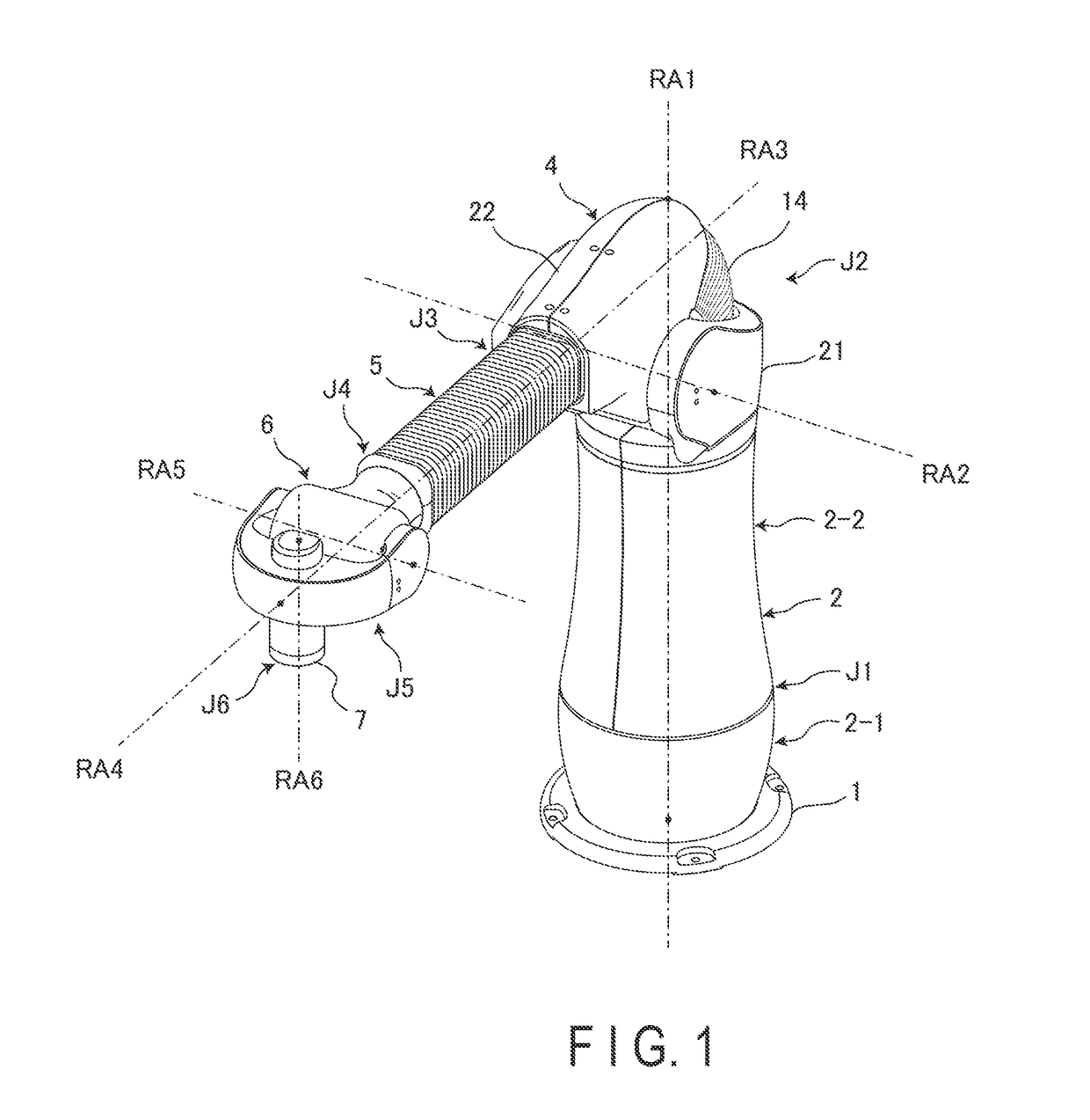
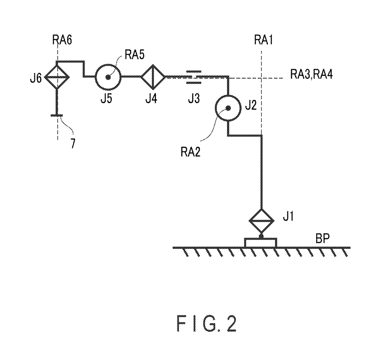
[0018]FIG. 1 illustrates an external appearance of the vertical articulated robot arm mechanism equipped with a linear extension and retraction mechanism according to the present embodiment. FIG. 2 illustrates a configuration of the robot arm mechanism using graphic symbol representation. A column 2 that forms a cylindrical body is typically installed vertically on a base stand 1 of the robot arm mechanism. The column 2 houses a first joint J1 serving as a turning joint. The first joint J1 includes a torsional rotation axis RA1. The axis of rotation RA1 is parallel to a vertical direction. As the first joint J1 rotates...


PUM


Abstract

In a robot arm mechanism, a column equipped with a turning joint is supported on a base stand, a rise / fall section equipped with a rise / fall joint is placed on the column, a linear extension and retraction mechanism equipped with a linearly extendible and retractable arm is provided on the rise / fall section, and the arm is equipped at a tip with a wrist section fittable with an end effector. The wrist section is made up of a combination of a roll joint used to swing the end effector, a pitch joint used to tilt the end effector back and forth, and a yaw joint used to axially rotate the end effector. At least two of the joints are each equipped with a mechanical stopper mechanism adapted to limit motion to within a mechanical operating range and with a safety stopper mechanism adapted to limit motion to within a safe range of movement narrower than the mechanical operating range.

Description

CROSS-REFERENCE TO RELATED APPLICATIONS[0001]This application is a continuation application of International Patent Application No. PCT / JP2017 / 002231 filed on Jan. 24, 2017, which is based upon and claims the benefit of priority from the prior Japanese Patent Application No. 2016-016759, filed Jan. 30, 2016 the entire contents of which are incorporated herein by reference.FIELD[0002]An embodiment of the present invention relates to a robot arm mechanism.BACKGROUND[0003]In recent years, the possibility of a situation in which an industrial robot, not to mention a nursing care robot, works in the vicinity of an operator has been studied. If such a situation is realized, handicapped persons can work similarly, for example, to non-handicapped persons. A vertical articulated robot arm mechanism equipped with a linear extension and retraction joint put to practical use by the inventors has neither an elbow joint nor a singularity, and thus implements an environment in which a robot system...

Claims


Application Information

Patent Timeline
Patent Type & Authority Applications(United States)
IPC IPC(8): B25J19/06B25J9/04B25J9/10B25J18/04
CPCB25J19/06B25J9/045B25J9/101B25J18/04B25J9/102B25J9/047B25J18/02
Inventor YOON, WOO-KEUNMATSUDA, HIROAKI
Owner LIFE ROBOTICS CO LTD
Learn More