
Printing on fibrous material

a technology of fibrous material and printing machine, which is applied in the direction of typewriters, duplicating/marking methods, and textiles and paper, etc., can solve the problems of increasing the cost, material to be printed wet, and difficult to manage chemical-physical characteristics, so as to minimize the treatment time of sheet fibrous material and quick treat the material. the effect of the material and reasonable operating cos

Active Publication Date: 2018-12-20
DOVER EURO SARL
View PDF4 Cites 3 Cited by
  • Summary
  • Abstract
  • Description
  • Claims
  • Application Information

AI Technical Summary

Benefits of technology

The invention is a plant and process for efficiently treating sheet fibrous materials, such as fabrics and non-woven fabrics, to prepare them for printing, particularly digitally. The plant includes a preparing station that wets and / or impregnates the material with pre-treatment substances such as thickening and anti-migration additives. The process also increases the surface hydrophobicity of the material, making it easier to print. The goal is to reduce treatment time and costs while maintaining high productivity.

Problems solved by technology

Actually, in the digital printing, jet heads having a plurality of nozzles having a small ink passage opening are used: in this situation, it is virtually impossible to directly add the ink because this latter could become, for example, too much viscous, which would prevent the ink from regularly passing through the heads, or could get chemical-physical characteristics which are not easily manageable by the systems controlling the same digital heads.
These pre-treatment substances are typically applied by dipping the fibrous material in suitable tanks or by spraying them on it: the present techniques inevitably leave the material to be printed wet.
Although the above cited apparatuses enable to pre-treat and print sheet fibrous materials, the Applicant has discovered that such apparatuses are however not devoid of some shortcomings and therefore are improvable under different aspects.
It is observed that these steps, besides complicating the structure of the plant and increasing the cost thereof, slow down the overall printing process with substantial shortcomings with reference to the production and therefore to the costs of a final product.

Method used


Image

  • Printing on fibrous material
  • Printing on fibrous material
  • Printing on fibrous material

Examples


first embodiment

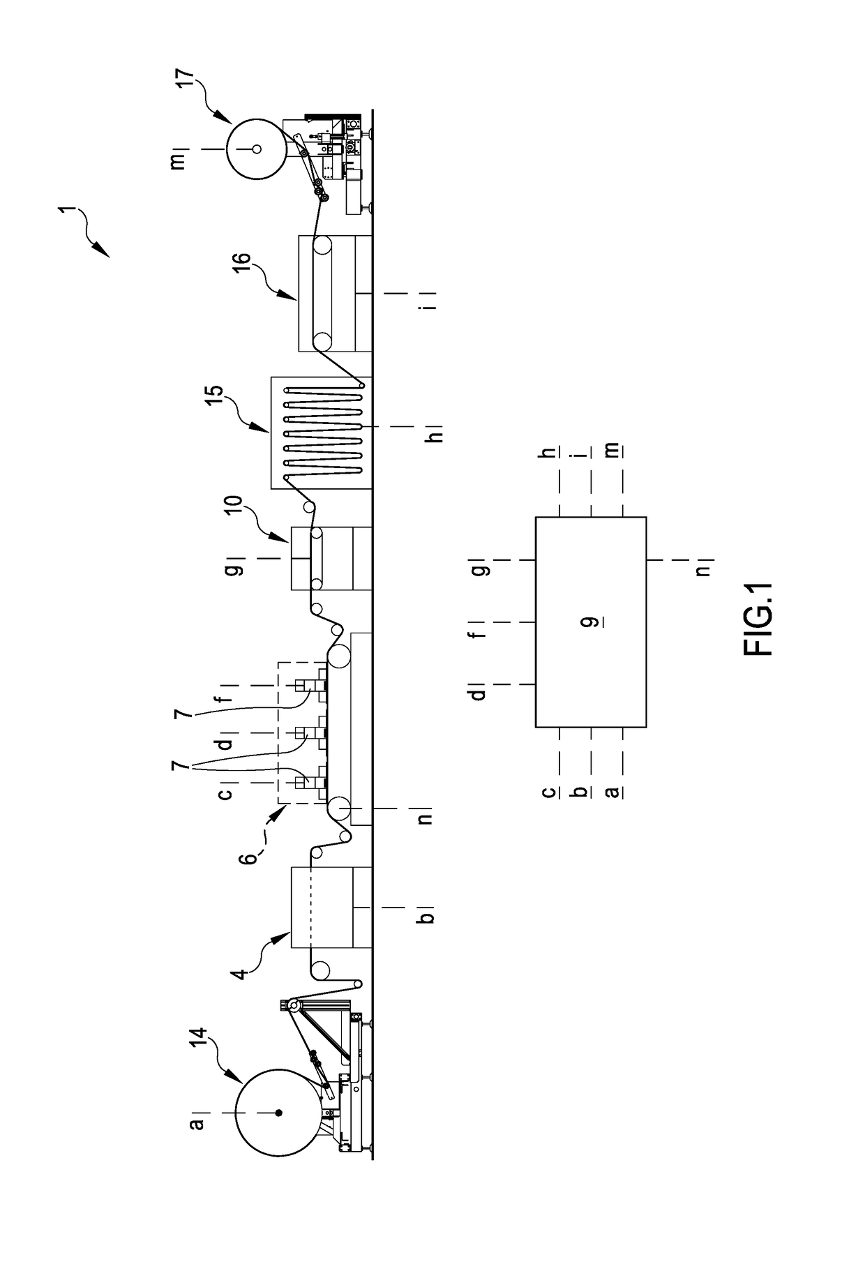
[0469]In a first embodiment, the preparing station 4 is configured for placing on the sheet fibrous material T a predetermined quantity of the treatment composition M comprising at least one of: a treatment liquid and treatment foam. As illustrated in FIG. 1, the preparing station 4 can be placed upstream the conveyor belt 2 so that the sheet fibrous material T is treated—by the treatment composition M—before the sheet fibrous material T itself comes in contact with the conveyor belt 2 (before the operative tract 3). FIG. 4 illustrates a further variant of the preparing station 4 wherein the same is placed at the conveyor belt 2: in this latter configuration, the preparing station 4 is configured for placing on the sheet fibrous material T, placed on the operative tract 3, the treatment composition M.

[0470]As hereinbefore described, in an embodiment of the invention, the conveyor belt 2 defines an operative condition wherein the same continuously moves the sheet fibrous material T c...

second embodiment

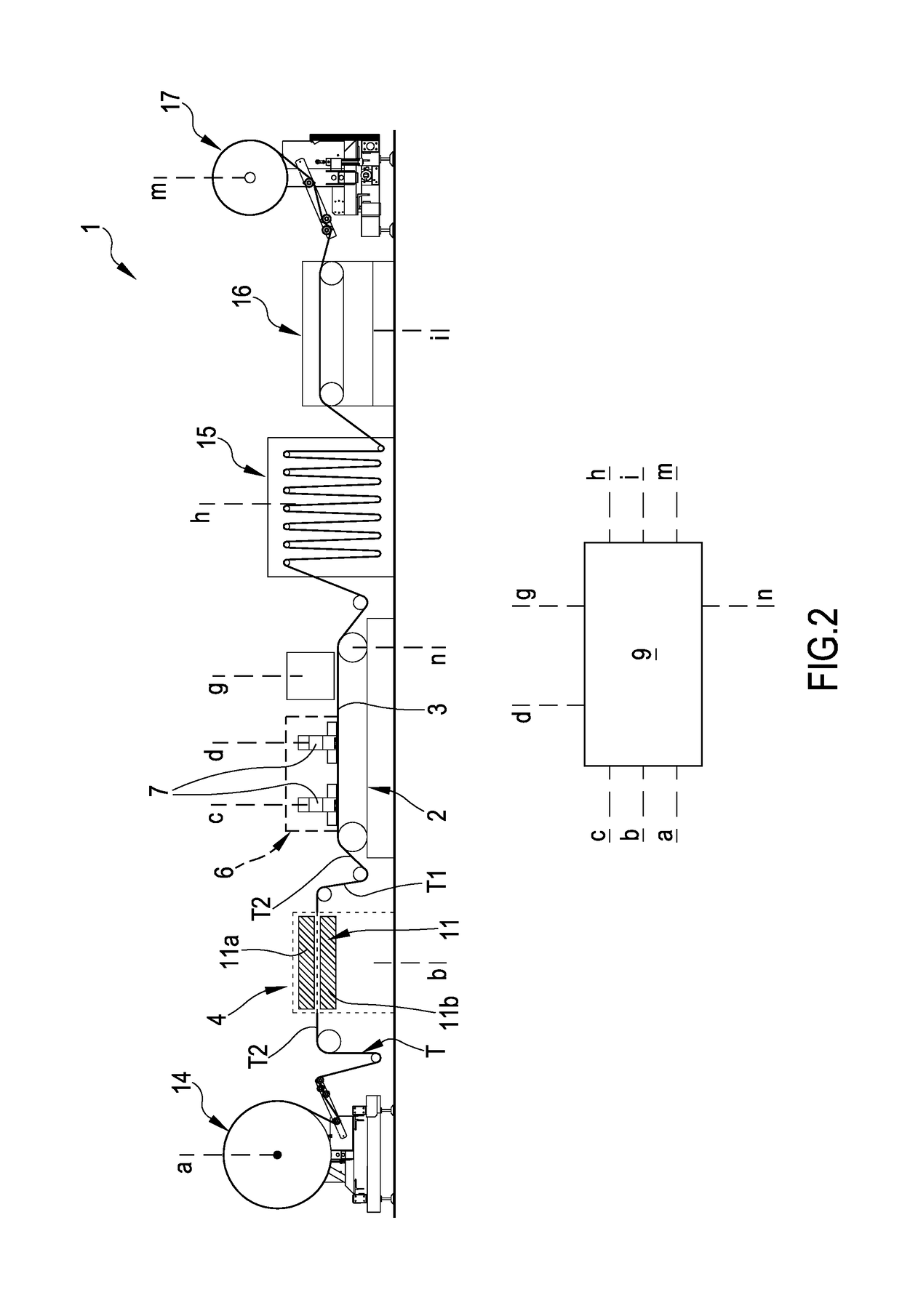
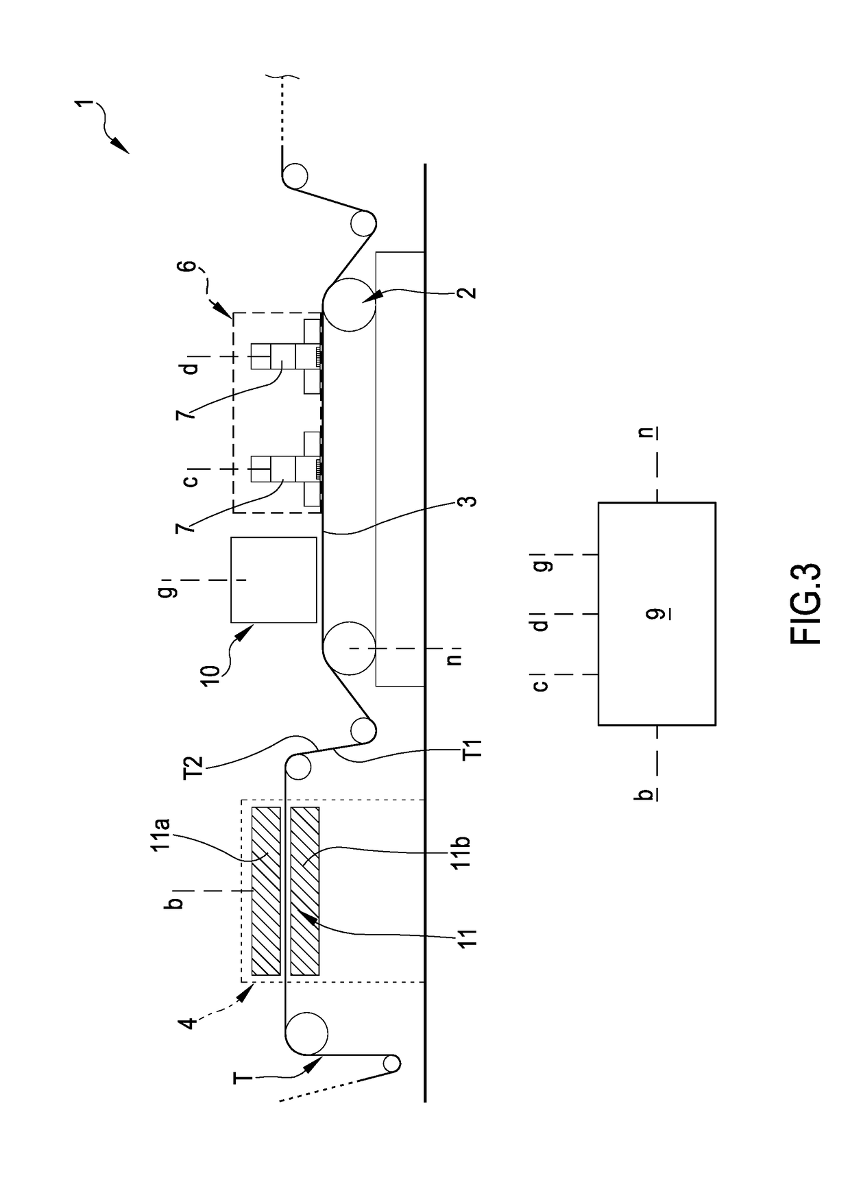
[0508]As hereinbefore described, in an embodiment of the invention, the conveyor belt 2 defines an operative condition wherein the same continuously moves the sheet fibrous material T constantly at a speed greater than 0; the preparing station 4 (in the second embodiment thereof) is configured for modifying the hydrophobicity of the fibrous material T, during the predetermined operative condition. More particularly, the preparing station 4 and printing station 6 are placed immediately consecutive to each other along the advancement direction A of the sheet fibrous material T; the conveyor belt 2, during the operative condition, is configured for continuously moving the sheet fibrous material T through the preparing station 4 and printing station 6. Particularly, between the preparing station 4 and printing station 6, it is not present a drying station.

[0509]The preparing station 4 (according to the described embodiment) comprises at least one plasma-treating device 11 configured for...


PUM

PropertyMeasurementUnit
speedaaaaaaaaaa
speedaaaaaaaaaa
constant speedaaaaaaaaaa

Abstract

The present invention refers to a plant (1) for printing, particularly for digitally printing, a sheet fibrous material (T), said printing plant (1) comprising: a conveyor belt (2) configured for receiving the sheet fibrous material (T) and guiding it in the movement along an advancement direction (A); a printing station (6) adapted to ink-print at least part of a second side (T2) of the sheet fibrous material (T); one preparing station (4) configured for modifying the surface hydrophobicity of at least part of the sheet fibrous material (T). The preparing station (4) comprises at least a plasma treating device (11) configured for define a treatment environment where at least a portion of the fibrous material is received and wherein ionized gas is present. The plant (1) comprises a control unit (9) actives on the conveyor belt (2) and on the plasma treating device (11); the control unit (9) being configured for: commanding the movement of the conveyor belt (2), controlling at least an operative parameter of the plasma treating device (11) as function of the movement of the conveyor belt (2). The present invention further refers to a process of printing of sheet fibrous material.

Description

FIELD OF THE INVENTION[0001]The present invention refers to a plant for printing, particularly for digitally printing, a fibrous material having a sheet-shape; the invention further refers to a process of printing, particularly of digitally printing, said sheet fibrous material. The plant and the associated process object of the invention can find an application in the field for printing fabrics and / or non-woven fabrics. The invention is generally, but in a non limiting way, applicable to the textile or knitted fabric or non-woven fabric industry.STATE OF THE ART[0002]As it is known, the conventional printing—in other words the one using printing silk-screen cylinders or frames—and the digital-type printing—in other words the one using one or more printing nozzle heads—are technologies used for applying inks or paints defining motives, patterns, colorations on sheet materials of different kind, such as for example, paper, fabrics, non-woven fabrics, fell, and more.[0003]The fabrics,...

Claims


Application Information

Patent Timeline
Patent Type & Authority Applications(United States)
IPC IPC(8): B41J11/00B41J3/407
CPCB41J11/002B41J11/007B41J3/4078B41J11/0015D06P5/2011D06P5/30D06P1/6491D06P1/653D06P1/673B41M5/0064B41M5/0047B41M5/0011
Inventor MILINI, LUIGI
Owner DOVER EURO SARL
Learn More